Analog signal transition detector

a technology of analog signal and detector, applied in the field of analog signal predefined transition detection apparatus, can solve the problems of compromising accurate zero crossing detection, low amplitude components of band limited signals, and difficult to achieve input value equality in practi

Inactive Publication Date: 2007-12-13
KENERGY INC
View PDF39 Cites 41 Cited by
  • Summary
  • Abstract
  • Description
  • Claims
  • Application Information

AI Technical Summary

Benefits of technology

[0027]In accordance with one aspect of the current invention, an apparatus is configured to detect transitions between relatively rising and falling amplitudes of an input signal Vin(t) contaminated with a noise signal n(t) arriving at a circuit input. That apparatus comprises a comparator circuit having first and second inputs and an output for providing a two-state output signal which changes states in response to the relatively rising amplitude of the input signal Vin(t) and the relatively falling amplitude of the input signal Vin(t). A delay circuit is configured to shift input signal by a predefined amount of time and applied that shifted signal to

Problems solved by technology

Equality of input values is very difficult to achieve in practice.
With low frequency contamination the “baseline” or “the zero line” may wander and compromise accurate zero crossing detection.
Nevertheless, a band limited signal contains low amplitude components from the stop bands, i.e. frequencies above or below the pass band, or noise.
The low frequency content would still be prevalent and cause inaccuracies in signal detection.
Such noise may cause erroneous detection of “zero crossings.”
Electrical shocks are uncomfortable and disconcerting to the patient in addition to causing some minor damage.
However, all these manipulations have fundamental limitations associated with the linear nature, computational complexity, or difficulty in real-time implementation as well as low sensitivity and specificity.
Moreover, discrimination of ventricular tachycardia from ventricular fibrillation is still a difficult object to achieve using conventional algorithms for ICD and AED.
These and other non-linear dynamics derived methods are based on the phase space reconstruction, and the computational demand and complexity are considerable for current ICD and AED, therefore, they are still difficult to apply in the real world.
Correlation dim

Method used


Image

  • Analog signal transition detector
  • Analog signal transition detector
  • Analog signal transition detector

Examples


Embodiment Construction

[0039]Although the present invention is described in the context of transition detection of physiological signals, the present signal feature detector may be used for a variety of signals, including but not limited to electrical, mechanical, acoustic and ultrasound signals. It is important that the input signal Vin(t) to the detector is a band limited signal.

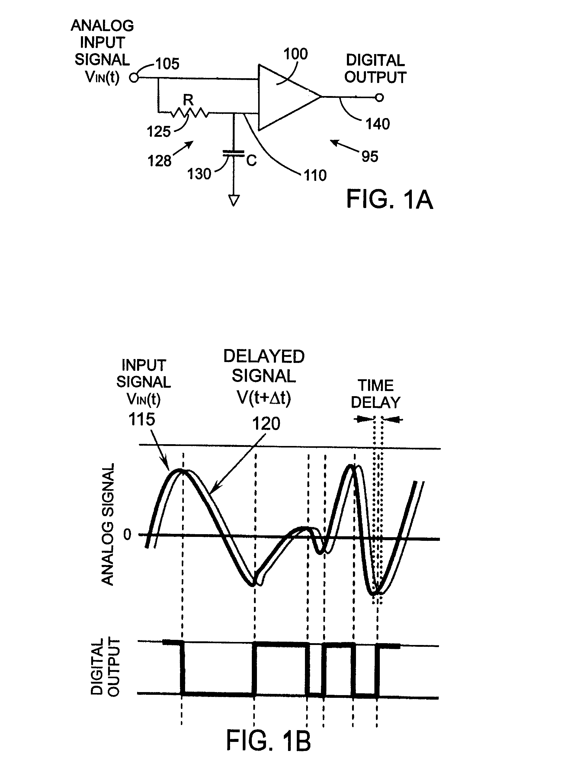
[0040]Initially, referring to FIGS. 1A and 1B, a hardware implementation of a signal feature detector 95 according to the present invention includes a comparator 100, which receives the input signal Vin(t) at and input node 105 to be containing transitions to be detected and receives a time-shifted version of that signal Vin(t+Δt) 110. An exemplary input signal Vin(t) is depicted by line 115 and with waveform 120 corresponding to the time-shifted signal Vin(t+Δt). In response to those signals, the comparator 100 identifies features in the input signal Vin(t) that are distinguished by having a local zero derivative representing t...


PUM


Abstract

An apparatus configured to detect transitions between relatively rising and falling amplitudes of an input signal Vin(t) arriving at a input node comprises a comparator having a first input, a second input, and an output for providing a two state output signal Vout(t) wherein state changes in the output signal Vout(t) correspond to the relatively rising amplitude of the input signal Vin(t) and the relatively falling amplitude of the input signal Vin(t). A delay circuit provides a shifted signal Vin(t+Δt) to the second input of the comparator, and a hysteresis circuit provides hysteretic deadband appended input signal Vin+ΔV to the first input of the comparator.

Description

CROSS-REFERENCE TO RELATED APPLICATIONS[0001]This application claims benefit of U.S. Provisional Patent Application No. 60 / 811,535 filed on Jun. 7, 2006, and U.S. Provisional Patent Application No. 60 / 811,536 filed on Jun. 7, 2006.STATEMENT REGARDING FEDERALLY SPONSORED RESEARCH OR DEVELOPMENT[0002]Not ApplicableBACKGROUND OF THE INVENTION[0003]1. Field of the Invention[0004]The present invention relates apparatus for detecting predefined transitions in analog signals, and more particularly to such apparatus that accurately detects small features in composite analog signals.[0005]2. Description of the Related Art[0006]A comparator is commonly used to compare two voltages and switches its output to indicate which voltage is greater. A standard operational amplifier without negative feedback can be used as a comparator. When the voltage is applied the non-inverting input (V+) of the operational amplifier is greater than the voltage at the inverting input (V−), the high gain of the ope...

Claims


Application Information

Patent Timeline
IPC IPC(8): G06F19/00A61B5/308
CPCA61B5/04012A61B5/0428H03F3/45475H03F2203/45136H03F2200/171H03F2200/78H03F2200/165A61B5/316A61B5/30
Inventor BULKES, CHERIKDENKER, STEPHEN
Owner KENERGY INC
Why Eureka
Try Eureka