Package wrapping method and apparatus

a packaging and packaging technology, applied in the field of packaging wrapping methods and apparatuses, can solve the problems of insufficient wrapping of random size gifts, machine work well, waste of materials, etc., and achieve the effects of convenient operation, minimal waste, and high quality

Inactive Publication Date: 2007-12-20
MET TECH CORP A CORP ORGANIZED UNDER THELAWS OF THE STATE OF MISSISSIPPI
View PDF12 Cites 36 Cited by
  • Summary
  • Abstract
  • Description
  • Claims
  • Application Information

AI Technical Summary

Benefits of technology

[0026] This two step dispensing of the paper web enables an operator to manually wrap a portion of the box, placing the cut sheet leading edge at a seam. This seam can easily be matched with the trailing edge of the wrapping paper when the second section of wrapping paper has been dispensed and then cut transversely. In so doing the package is encircled and wrapped with the cut sheet to cover the box top, bottom, front and rear. The operator then finishes the wrap by hand folding the end folds (i.e. sides of the paper web) inwardly to cover the box or package ends.
[0038] The present invention enables a package to be wrapped that is very heavy, limited only by the maximum package weight that can be handled safely by the operator.

Problems solved by technology

They are usually suited to a particular purpose, and have their limitations when attempts are made to apply them to other purposes.
The machine works well in the supermarket for wrapping butchered meat, but would not do an adequate job of wrapping articles of random size, such as gifts in boxes.
If it is attempted to meet the requirement by using precut sheets which are large enough to accommodate the largest box, difficulty will be encountered in presenting a neat appearance in the wrapped package for boxes which are smaller than the maximum size.
It is labor intensive, sometimes incapable of keeping up with peak demands, and oftentimes subject to variable quality of finished product.

Method used


Image

  • Package wrapping method and apparatus
  • Package wrapping method and apparatus
  • Package wrapping method and apparatus

Examples


Embodiment Construction

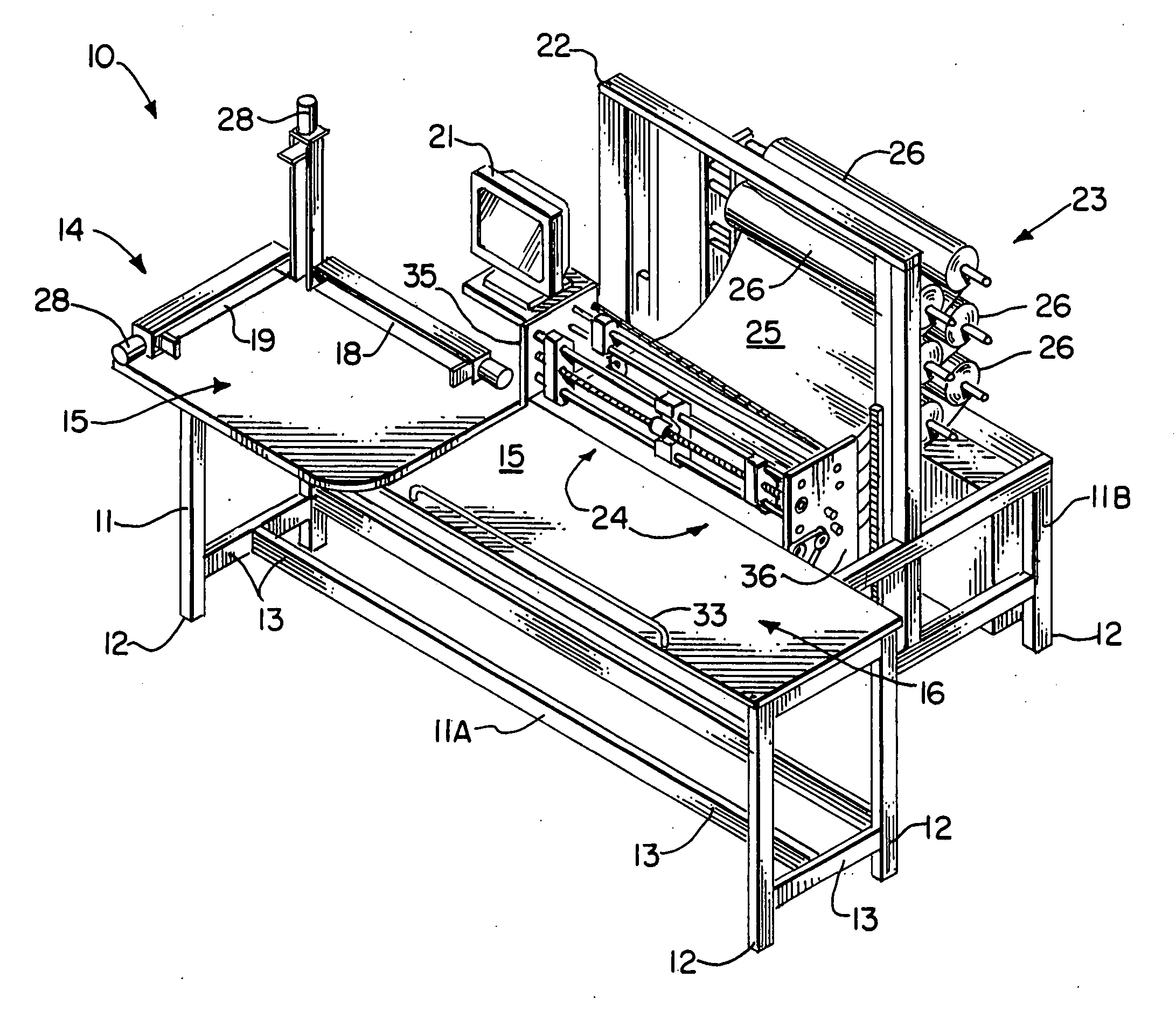
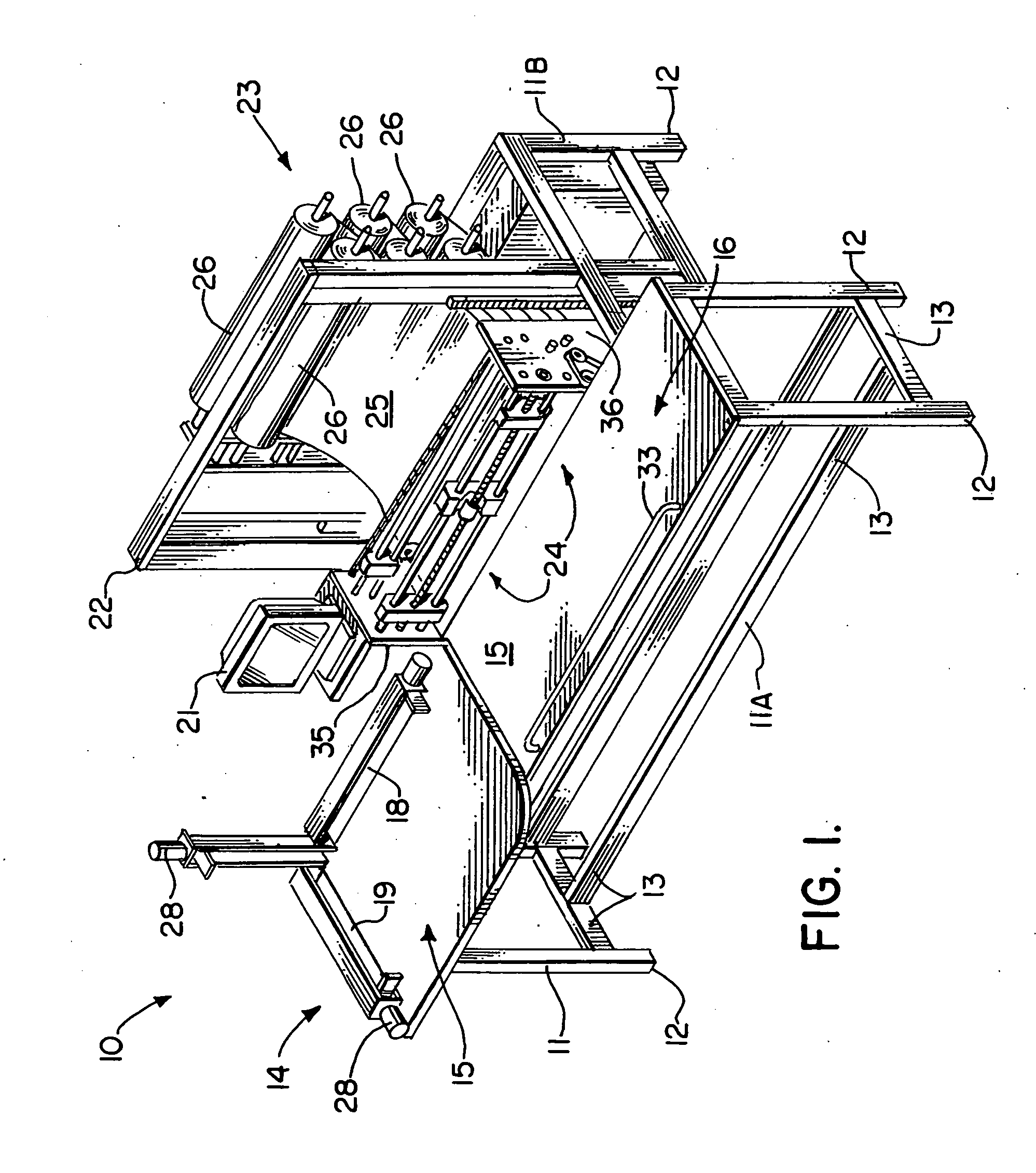
[0057]FIG. 1 shows generally the preferred embodiment of the apparatus of the present invention designated generally by the numeral 10. Gift wrapping apparatus 10 includes a structural frame 11 that can be of welded steel or the like. Frame 11 is comprised generally of a front frame section 11A and a rear frame section 11B. The frame 11 can be comprised of a plurality of vertical members that can include legs 12 and a plurality of transverse or horizontal supports 13.

[0058] Frame 11 is provided with a measuring station 14, wrapping station 16, paper supply 23, and a paper feed and cutting mechanism 24. At measuring station 14, a pair of stop bar members 18, 19 are provided along two edges of measuring station 14 work surface 15 as shown in FIG. 1. The stop bar members 18, 19 preferably define an angle of 90 degrees. When a package 20 is to be wrapped, it is first placed on work surface 15 of measuring station 14. A side and an end of the box of package 20 are placed respectively ag...


PUM

PropertyMeasurementUnit
angleaaaaaaaaaa
sizesaaaaaaaaaa
timeaaaaaaaaaa

Abstract

A semi-automatic gift or package wrapping method and apparatus is disclosed. The apparatus includes a machine frame that provides a work surface with measuring and wrapping sections. A sheet feed and cutting mechanism feeds paper from a role in two steps with a time pause in between for enabling a user or operator to partially wrap the package with part of the first section of dispensed paper web. Thereafter, the second section of paper web is dispensed and the web cut transversely at a trailing edge. Multiple selectable supply rolls are optionally provided, or a single roll machine can be used. Longitudinal cutters trim the sides of the paper to obtain a custom desired width for the full cut sheet. A user interface display controls machine functions such as start, continue and sheeter. In the sheeter mode, a selected number of sheets of a selected size can be dispensed and cut for use at another workstation to warp other boxes of known uniform size (i.e. shirt boxes at a department store).

Description

CROSS-REFERENCE TO RELATED APPLICATIONS [0001] This is a continuation of U.S. patent application Ser. No. 10 / 256,468, filed Sep. 27, 2002, now U.S. Pat. No. 6,938,397, and incorporated herein by reference.STATEMENT REGARDING FEDERALLY SPONSORED RESEARCH OR DEVELOPMENT [0002] Not applicable REFERENCE TO A “MICROFICHE APPENDIX”[0003] Not applicable BACKGROUND OF THE INVENTION [0004] 1. Field of the Invention [0005] The present invention relates to a method and apparatus for wrapping articles such as boxes and more particularly to an improved method and apparatus for semi-automatically wrapping boxes of differing or random sizes in sequence, wherein the box to be wrapped is automatically measured, its dimensions optionally displayed on a user interface screen, and wherein a first section of a full sheet of paper web is dispensed from a supply roll for enabling an operator to partially wrap the box that was previously measured, followed by a further dispensing of the sheet of paper web ...

Claims


Application Information

Patent Timeline
Patent Type & Authority Applications(United States)
IPC IPC(8): B65B11/02B65B11/00B65B67/08G06Q10/04
CPCB65B11/18G06Q10/043B65B67/10B65B67/08B65B11/004B65B2210/04B65B59/001
Inventor MILLER, MICHAEL E.
Owner MET TECH CORP A CORP ORGANIZED UNDER THELAWS OF THE STATE OF MISSISSIPPI
Why Eureka
Try Eureka