

Fuel Supply Apparatus and Vehicle Provided with the Same
a technology of fuel supply and fuel jet, which is applied in the direction of applications, transportation items, combustion air/fuel air treatment, etc., can solve the problem of short fuel feed rate, and achieve the effect of improving engine performance and promoting fuel jet atomization
- Summary
- Abstract
- Description
- Claims
- Application Information
AI Technical Summary
Benefits of technology
Problems solved by technology
Method used
Image

Examples
first embodiment
[0046] An embodiment of the invention will be described below in detail with reference to the drawings.
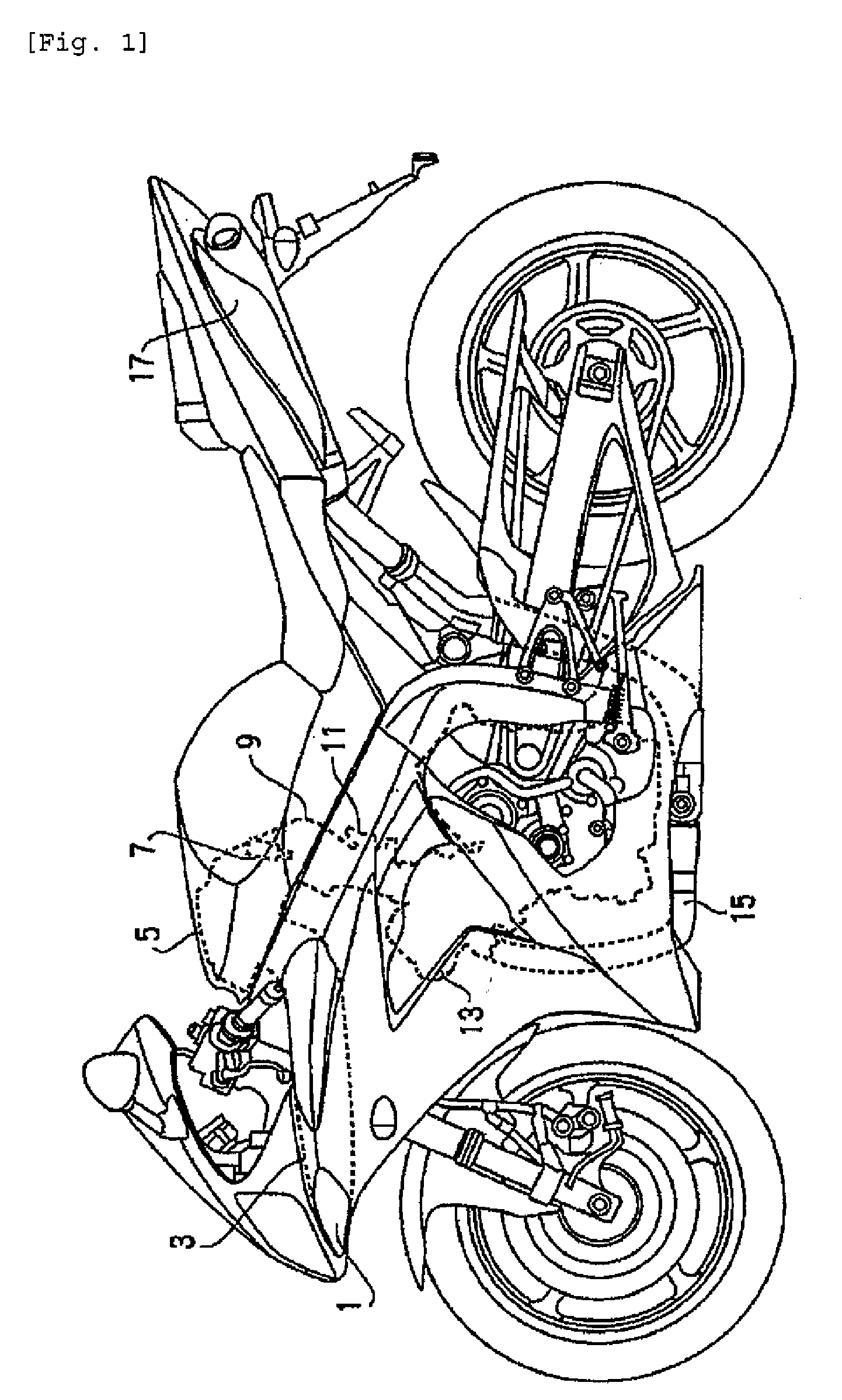
[0047]FIG. 1 is a side view showing an example of a vehicle according to the embodiment of the invention. The vehicle according to the embodiment comprises a motorcycle (including motorbikes, scooters, etc.). In the figure, the left indicates the front of a vehicle and the right indicates the rear of a vehicle. In addition, front and rear, and left and right referred to in the specification of the present application mean front and rear, and left and right with a person, who rides a vehicle, as reference.
[0048] The motorcycle comprises an inlet port 1, through which an air is taken, an air cleaner 5, an engine 13, and a muffler 17. The inlet port 1 and the air cleaner 5 are connected to each other through an intake duct 3. The air cleaner 5 and a combustion chamber 13c (not shown in FIG. 1. see FIG. 2) of the engine 13 are connected to each other through intake passages 9. The co...
second embodiment
[0126] A fuel supply apparatus according to a second embodiment will be described with reference to FIGS. 11 to 14. In addition, the same portions as those in the first embodiment are denoted by the same reference numerals as those in the latter, and a detailed explanation therefor is omitted.
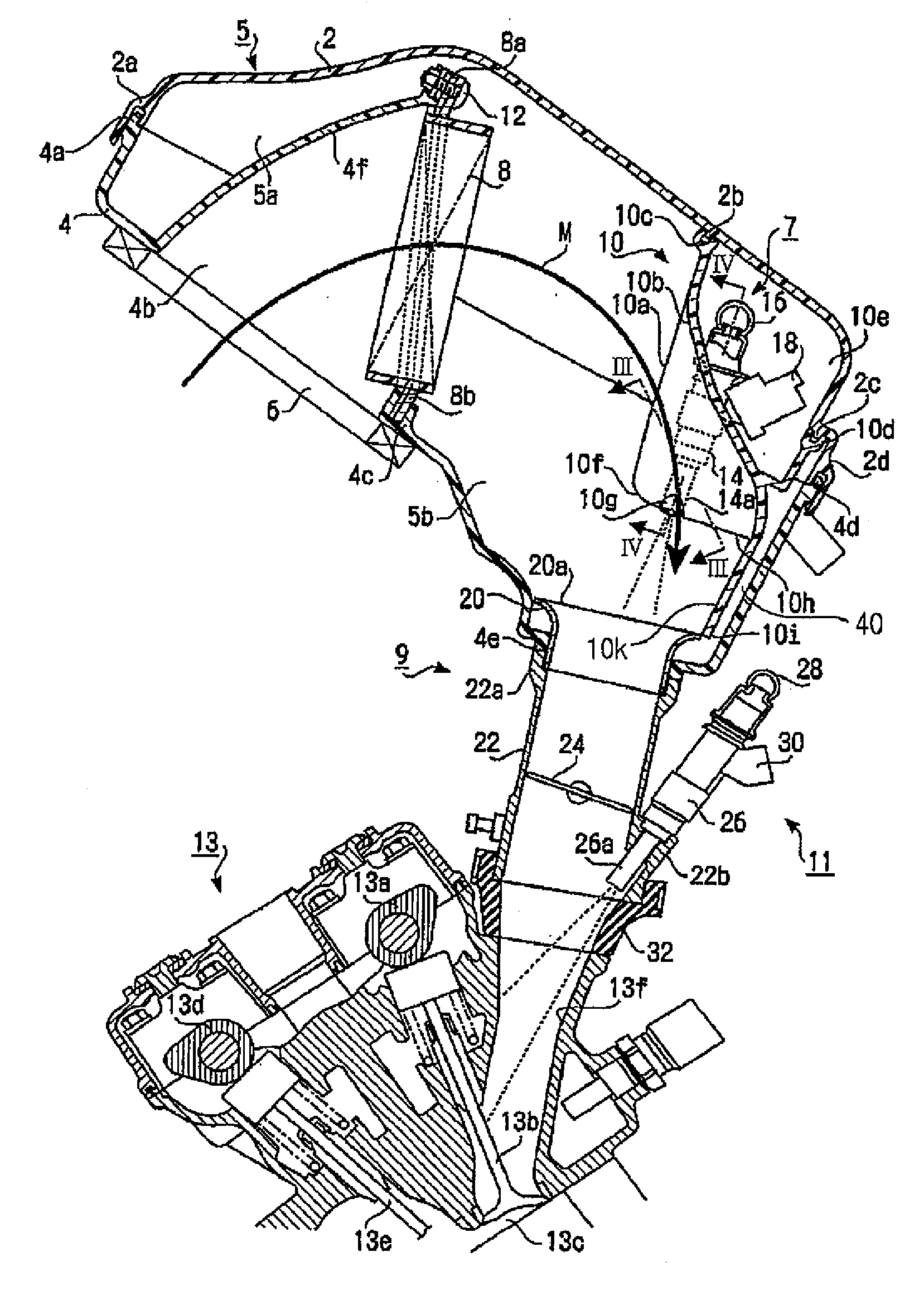
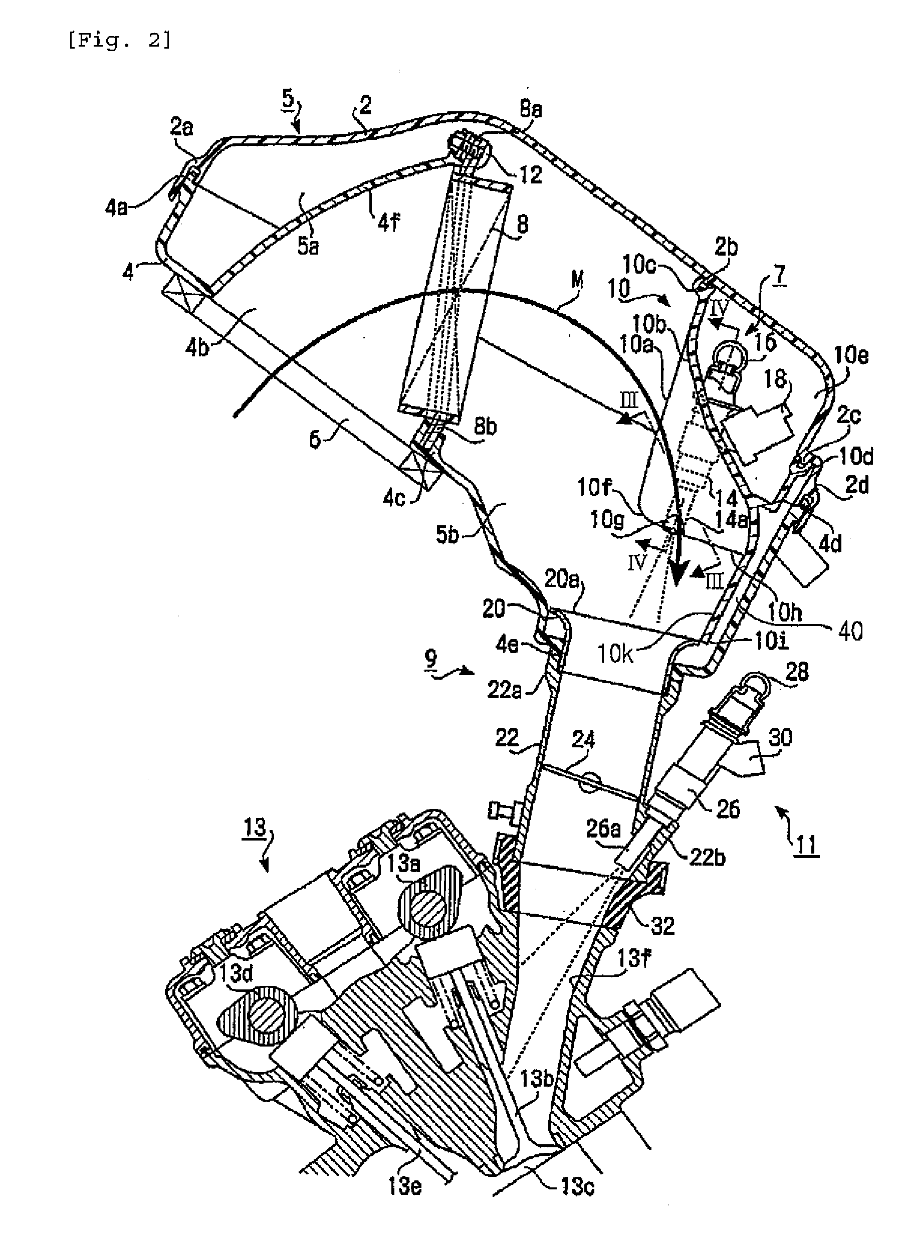
[0127] According to the first embodiment, the lower ends 10i of the extension walls 10k are extended to substantially the same level of ends of the openings 20a of the air funnels 20 (see FIG. 2). In contrast, as shown in FIGS. 12 and 13, according to the second embodiment, lower ends 10i of extension walls 10k are positioned above openings 20a of air funnels 20. That is, clearances are formed between the extension walls 10k and the openings 20a in a direction, in which the openings 20a are opened (a vertical direction in FIG. 12).
[0128] As shown in FIG. 12, according to the embodiment, an injector bracket 10 is arranged in a main chamber 5b of an air cleaner 5 and separate chambers 10e are f...
third embodiment
[0143] According to the first and second embodiments, the extension walls 10k are provided on the injector bracket 10. That is, a part of the injector bracket 10 constitutes the extension walls 10k. However, extension walls 10k may be separate from an injector bracket 10. As shown in FIG. 15, according to a third embodiment, the extension walls 10k are formed separately from the injector bracket 10.
[0144] In FIG. 15, the right indicates the front of a vehicle and the left indicates the rear of a vehicle. According to the embodiment, an air cleaner 5 comprises an upper casing 2 and a lower casing 4, and an intake port 4b is formed on the front of the lower casing 4. Formed in the air cleaner 5 is a flow passage curved in a substantially inverted U-shaped manner.
[0145] According to the third embodiment, the injector bracket 10 is arranged inside the curved flow passage (toward a center of curvature). The injector bracket 10 is formed to assume a shape of a cylinder extending in a le...
PUM
 Abstract
Description
Claims
Application Information