Heat sink and method of making same

a heat sink and heat sink technology, applied in lighting and heating apparatus, cooling/ventilation/heating modification, electrical equipment, etc., can solve the problems of undesirable thermal gradient generation, reducing the conductivity of the cooled edges reducing the conductivity of the cooled edge of the cold plate, etc., to achieve less complex, less expensive, and low risk

Active Publication Date: 2007-12-20
RAYTHEON CO
View PDF18 Cites 44 Cited by
  • Summary
  • Abstract
  • Description
  • Claims
  • Application Information

AI Technical Summary

Benefits of technology

[0019]The present invention thus provides a unique way to control thermal gradients and to produce an isothermal heat transfer surface. The surface temperature increases, but remains uniform. This uniform temperature is present even if, in one example, the power or duty cycle of a phased array radar system—with which the present invention may be used—is increased. The present invention thus provides a less expensive, less complex device which solves the thermal gradient problem. Also, because no brazing is required, the present invention allows for the use of extruded or gun drilled manifolds for the heat sink which are very low risk compared to brazed aluminum manifolds.

Problems solved by technology

The gain changes approximately 0.1 dB / ° C. and the phase changes approximately 0.8° / ° C. Thus, controlling thermal gradients in phased array radar systems is an important and challenging requirement to meet.
The tabs include orifices therethrough which are aligned with orifices in the skins of the cold plate, thus reducing the conductivity of the cooled edges of the cold plate.
Thus, an undesirable thermal gradient is generated at this level of the phased array radar system as well.
These brazed manifolds / heat sinks provide distinct disadvantages, however.
One disadvantage is that the tailored heat passages provide a “calibration” that is only effective for a single heat dissipation.
Moreover, because of the complex cooling channel geometry; including tailored heat transfer passages, cooling channels designed to take advantage of techniques of cross or counter flow, or designs which “shift” coolant away from some components; brazed aluminum manifolds are expensive, typically have long lead times, and in some cases can be difficult to manufacture.
An additional disadvantage of such heat sinks or manifolds follows from that fact that vacuum brazing furnaces are limited in size.
Thus, for larger arrays manufacturing becomes more difficult and expensive.

Method used


Image

  • Heat sink and method of making same
  • Heat sink and method of making same
  • Heat sink and method of making same

Examples


Embodiment Construction

[0047]Aside from the preferred embodiment or embodiments disclosed below, this invention is capable of other embodiments and of being practiced or being carried out in various ways. Thus, it is to be understood that the invention is not limited in its application to the details of construction and the arrangements of components set forth in the following description or illustrated in the drawings. If only one embodiment is described herein, the claims hereof are not to be limited to that embodiment. Moreover, the claims hereof are not to be read restrictively unless there is clear and convincing evidence manifesting a certain exclusion, restriction, or disclaimer.

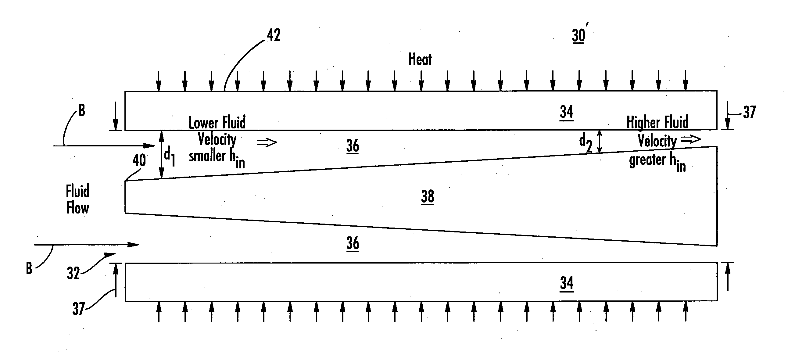
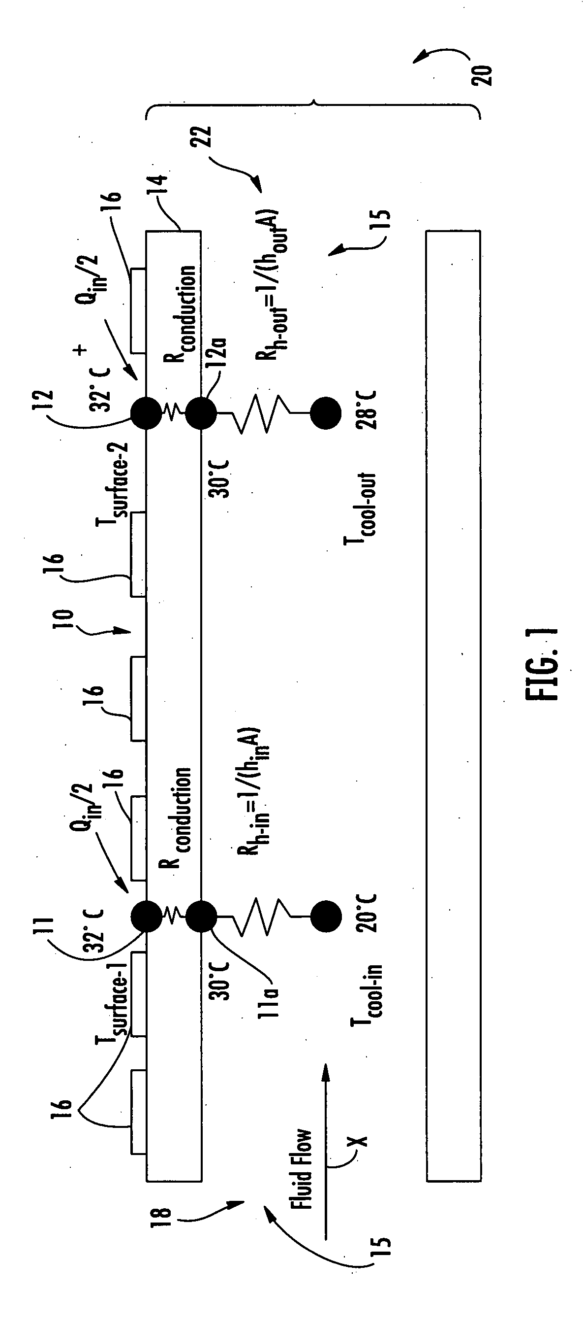
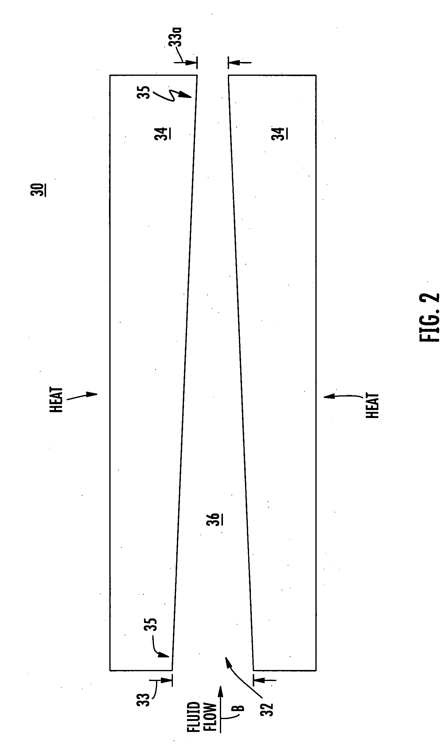
[0048]As discussed in the Background section above, thermal gradients occur in fluid cooled heat sinks because, as the fluid travels through the heat sink, it picks up heat from the heat sources. Consequently, the coolant further downstream is at a higher temperature. This condition is shown schematically in FIG. 1. In this...


PUM


Abstract

A heat sink includes a fluid channel and a cooling wall in contact with coolant flowing in the fluid channel. The channel is configured to vary the velocity of coolant along the length of the fluid channel to vary the coolant's heat transfer coefficient and thereby compensate for the coolant's temperature rise along the length of the fluid channel. The result is a heat sink that is isothermal along its length.

Description

GOVERNMENT RIGHTS[0001]This invention was made with U.S. Government support under Contract No. Q1-19041-011 awarded by the United States Navy. The Government may have certain rights in the subject invention.FIELD OF THE INVENTION[0002]The subject invention relates to the control and reduction of thermal gradients, and, in one example, to a heat sink which may be used in a phased array radar system.BACKGROUND OF THE INVENTION[0003]Phased array radar systems employ amplifiers and phase shifters to electronically steer radio frequency (RF) beams, in contrast to the more familiar rotating radar dish. By using phase shifts, phased array radar systems eliminate the time delay between signals that is typically associated with rotating systems as the dish rotates 360°. Thus, phased array radar systems result in improved performance.[0004]One key parameter governing the RF performance of a phased array radar system, however, is the temperature or thermal gradient at all levels of the system....

Claims


Application Information

Patent Timeline
Patent Type & Authority Applications(United States)
IPC IPC(8): H05K7/20
CPCF28D2021/0029H05K7/20254F28F13/08
Inventor MCCORDIC, CRAIG H.LUDWICK, LEO S.
Owner RAYTHEON CO
Why Eureka
Try Eureka