
Sealing apparatus for a slag door of a metallurgical furnace

Inactive Publication Date: 2007-12-20
EMPCO (CANADA) LTD
View PDF3 Cites 15 Cited by
  • Summary
  • Abstract
  • Description
  • Claims
  • Application Information

AI Technical Summary

Benefits of technology

[0012] Advantageously, the apparatus also comprises at least one wiping component moveable so as to sweep across the lower surface of the slag door from an open position, remote from the slag door opening, through intermediate positions, to a closed position, within the slag door opening, such that the wiping component can remove obstructions from the lower surface of the slag door.
[0014] In certain embodiments, the closure element includes a gate supported by at least one parallelogram linkage mechanism such as the type having a motoring lever connected to a drive shaft, and a follower lever connected between the motoring lever and the closure element. The hot face panel of the gate is advantageously water cooled, and the gate may also include a water cooled bottom panel. In certain embodiments the water cooled bottom panel of the gate is pivotally mounted and can be activated to aid in breaking up and removing obstructions from the slag door.

Problems solved by technology

Slag can also freeze in large quantities in the area of the tunnel and the threshold of the slag door opening.
Commonly, operators must regularly try to clean out these areas by means of tractors equipped with long projecting rams, a technique that has limited efficacy and is also potentially dangerous for the operating personnel.
Such closure mechanisms are vulnerable to jamming and blockages, and after being in service for some time, they typically provide only partial coverage of the slag door opening.
As a result, ambient air is sucked into the furnace through the slag door which is believed to lead to a number of drawbacks, including:
uncontrolled decanting of slag through the slag door.

Method used


Image

  • Sealing apparatus for a slag door of a metallurgical furnace
  • Sealing apparatus for a slag door of a metallurgical furnace
  • Sealing apparatus for a slag door of a metallurgical furnace

Examples


Embodiment Construction

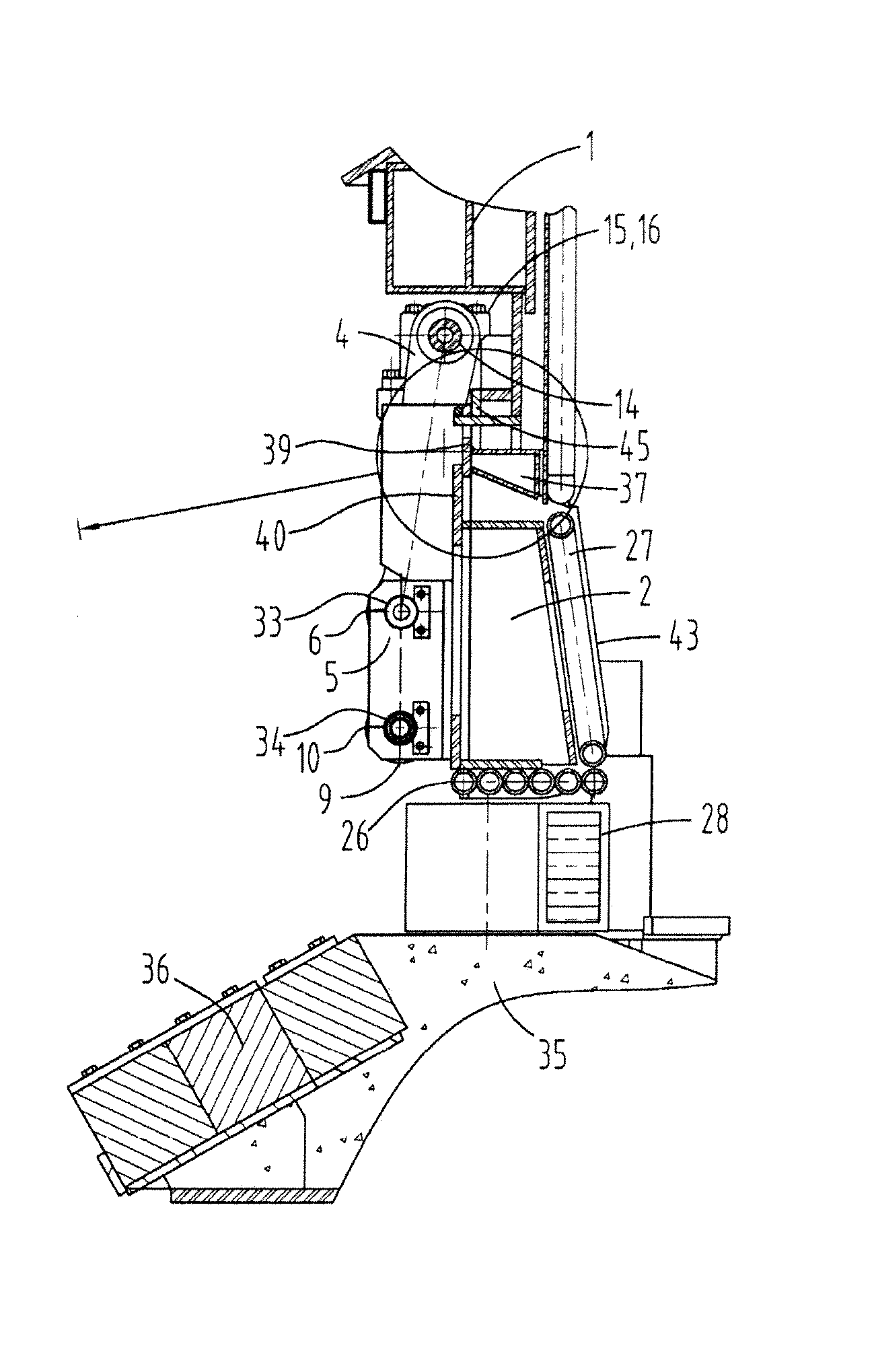
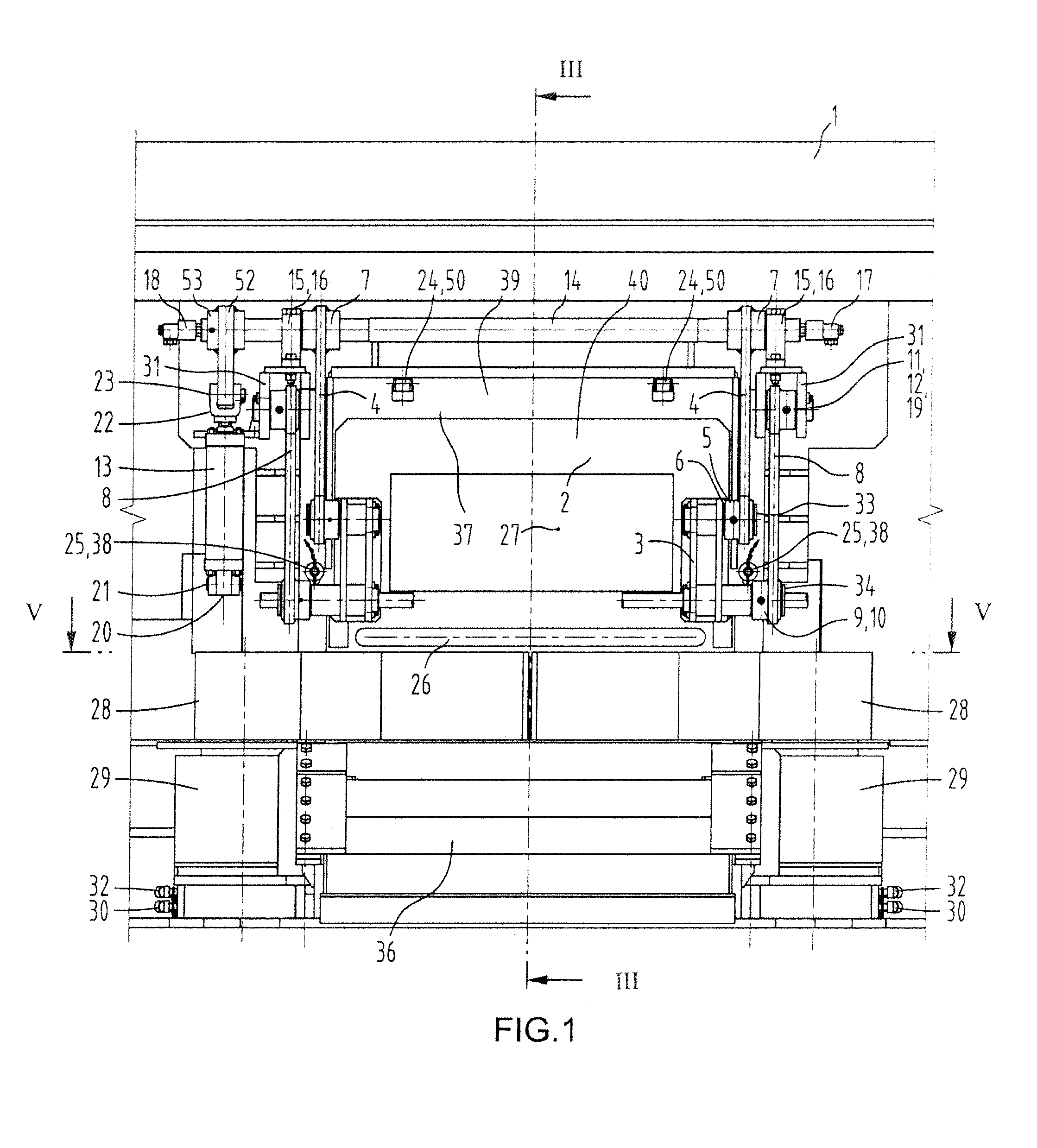
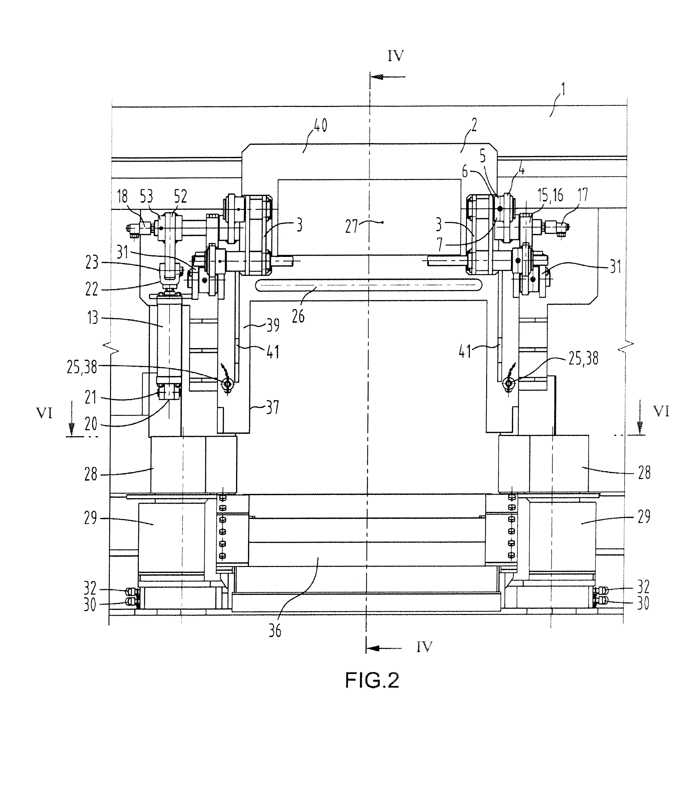
[0035] Referring to FIGS. 1-7, particularly FIG. 1, the sealing apparatus has two major component subassemblies, a rotating and retractable centrally located gate 2 controlled by two sets of rotating parallelogram levers (4, 8), and a pair of generally horizontally gyrating flipper arms 28, located below the gate 2.

[0036] One end of each of the motoring levers 4 is firmly attached to a driving shaft 14 via double-keyed hubs 7. The other end of each of the motoring levers 4 is equipped with hub 5 and it is dressed with lubricated friction bushing 6. The stabilized end of each follower levers 8 is equipped with hub 11, dressed with lubricated friction bushing 12, rotating around pin 19. The rotating ends of the follower levers 8 are equipped with hubs 9, dressed with lubricated friction bushings 10, rotating around hollow pins 34. The motoring levers 4 are connected to the double-bracket 3 of the gate 2 via pins 33 held firmly in the double-brackets 3. The follower levers 8 are conne...


PUM


Abstract

A sealing apparatus for a slag door of a metallurgical furnace, having a mounting assembly for mounting the apparatus to the furnace, and at least one closure element, moveable from an open position that is exterior of the slag door opening, to a closed position that effectively seals against the slag door and extends into the slag door opening with the rear panel of the closure element(s) being proximally aligned with the interior wall of the furnace. The apparatus may also have at least one wiping component moveable so as to sweep across the lower surface of the slag door to remove obstructions.

Description

BACKGROUND [0001] The present invention relates to metallurgical furnaces. In particular, the invention relates to metallurgical furnaces of the type having a slag door, such as electric arc furnaces used for steelmaking. [0002] Metallurgical furnaces of the type having a slag door are well known. The slag door is typically positioned on the side of the furnace shell with a tunnel area leading from the furnace interior, and an apron extending below the opening on the exterior of the furnace. The slag door is used for periodic tapping of slag by tipping the furnace, but it is also used for many other operations, including charging of additives, sample collecting, temperature measurement, insertion of burners and oxygen lances, and visual inspection of the furnace interior. [0003] In steelmaking operations, unmolten scrap metal tends to accumulate in the tunnel that extends through the furnace wall from the furnace interior to the slag door opening. Slag can also freeze in large quant...

Claims


Application Information

Patent Timeline
IPC IPC(8): C21C5/46
CPCF27B3/19F27D3/15F27D1/18
Inventor WUNSCHE, EDGAR R.
Owner EMPCO (CANADA) LTD
Learn More