Method and device for driving LED-based backlight module

a technology of led-based backlight modules and light-emitting diodes, which is applied in static indicating devices, instruments, non-linear optics, etc., can solve the problems of difficult control of the color temperature of the white light produced by these colored leds, limited improvement, and the difference between the brightness of individual leds, so as to increase the brightness of other working leds

Inactive Publication Date: 2007-12-20
VASTVIEW TECH
View PDF3 Cites 89 Cited by
  • Summary
  • Abstract
  • Description
  • Claims
  • Application Information

AI Technical Summary

Benefits of technology

[0007]The proposed device contains a driver controller which receives the timing signals from the display device and a number of drivers which is series-connected or parallel-connected to the driver controller. Each of the drivers is activated by the driver controller to drive a number of LEDs of the backlight module by current pulses. The duty cycle and the pulse count within a period of time (e.g., a frame time) of the current pulses are adjustable dynamically. Each driver automatically detects its output current or voltage and, in a constant-current or constant-voltage manner, increases the duty cycle of the current pulses so as to compensate the brightness loss from out-of-work LEDs by increasing the brightness of other working LEDs.

Problems solved by technology

One major drawback of the LED-based, direct-lit backlight module is that there is always some difference between the brightness of the individual LEDs.
When red-, green, and blue-light LEDs are used as light source, such difference is especially obvious and therefore it is difficult to control the color temperature of the white light produced by these colored LEDs.
Though the diffusion sheet is effective in smoothing out the difference, the improvement is still limited.

Method used


Image

  • Method and device for driving LED-based backlight module
  • Method and device for driving LED-based backlight module
  • Method and device for driving LED-based backlight module

Examples


Embodiment Construction

[0027]The following descriptions are exemplary embodiments only, and are not intended to limit the scope, applicability or configuration of the invention in any way. Rather, the following description provides a convenient illustration for implementing exemplary embodiments of the invention. Various changes to the described embodiments may be made in the function and arrangement of the elements described without departing from the scope of the invention as set forth in the appended claims.

[0028]The present invention provides a device and a related method for driving a direct-lit backlight module using multiple LEDs as light source. The backlight module could be one for a LCD device, a plasma display device, or an organic light-emitting display (OLED) device. For simplicity, the following description mainly uses a LCD device as example.

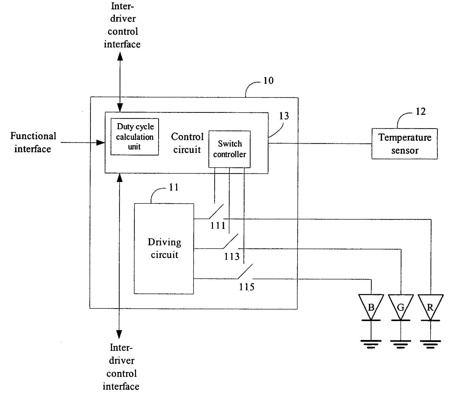
[0029]The device mainly contains a driver controller and a number of drivers. Each driver in turn controls a portion of the LEDs of the backlight modul...


PUM

PropertyMeasurementUnit
brightnessaaaaaaaaaa
frequencyaaaaaaaaaa
timeaaaaaaaaaa

Abstract

A device and a related device for driving LED-based, direct-lit backlight modules are provided. The device contains a driver controller which receives the timing signals from the display device and a number of drivers which is series-connected or parallel-connected to the driver controller. Each of the drivers is activated by the driver controller to drive a number of LEDs of the backlight module by current pulses. Each driver automatically detects its output current or voltage and increases the duty cycle of the current pulses so as to compensate the brightness loss from out-of-work LEDs. The method delivers pulses of different pulse counts in a fixed period of time (e.g., a frame time) to the red-, green-, and blue-light LEDs so as to achieve a constant color temperature based on their different response to the temperature.

Description

BACKGROUND OF THE INVENTION[0001]1. Field of the Invention[0002]The present invention generally relates to backlight modules for display devices, and more particularly to a device and a related method for driving the light emitting diodes of a direct-lit backlight module.[0003]2. The Prior Arts[0004]Currently, most backlight modules for large-sized liquid crystal displays (LCDs) or LCD TVs adopt a direct-lit approach using either cold cathode fluorescent lamps (CCFLs) or light emitting diodes (LEDs) as light source. As the CCFLs suffer potential environmental issues from the mercury vapor contained in the lamp tubes, while the LEDs have been advanced to provide superior switching speed, lighting efficiency, and cost, LEDs have become the main stream light source for LCDs. FIG. 1a is a schematic diagram showing a conventional LED-based, direct-lit backlight module. As illustrated, multiple LEDs are arranged in an array in front of a reflection plate. These LEDs could be white-light L...

Claims


Application Information

Patent Timeline
Patent Type & Authority Applications(United States)
IPC IPC(8): G02F1/1335
CPCG09G3/32G09G3/3413G09G2320/04G09G2330/08G09G2320/064G09G2320/0666G09G2320/041
Inventor SHEN, YUH-REN
Owner VASTVIEW TECH
Why Eureka
Try Eureka