Serial communication system with baud rate generator
a serial communication and baud rate technology, applied in the field of serial communication system correction, can solve the problems of deteriorating transfer speed, inability to determine accurate baud rate based on protocol, large etc., to reduce the error of baud rate, improve the transfer speed of serial communication, and lighten the load on the cpu
- Summary
- Abstract
- Description
- Claims
- Application Information
AI Technical Summary
Benefits of technology
Problems solved by technology
Method used
Image

Examples
first embodiment
[0043]FIG. 3 is a block diagram showing the configuration of a baud rate generator 12A in the serial communication system according to the first embodiment of the present invention. The master node 100 and the slave node 200 in the first embodiment include baud rate generators 12A in place of the baud rate generator 12.
[0044] Referring to FIG. 3, the baud rate generator 12A includes an edge detector 21, an edge counter 22, a synch field measuring timer 23, a baud rate correcting circuit 24A, a baud rate correction value register 25, a baud rate initial value setting register 26, a selector 27, a coincidence detecting circuit 29, and a counter 28.
[0045] When a synch brake field (L level of 11 bits or more) is supplied to the slave node 200, a synch brake field detection signal 30 is supplied to the edge detector 21 from a circuit (not shown). The edge detector 21 starts a falling edge detecting operation of the serial data on the bus 300 in response to the synch brake field detecti...
second embodiment
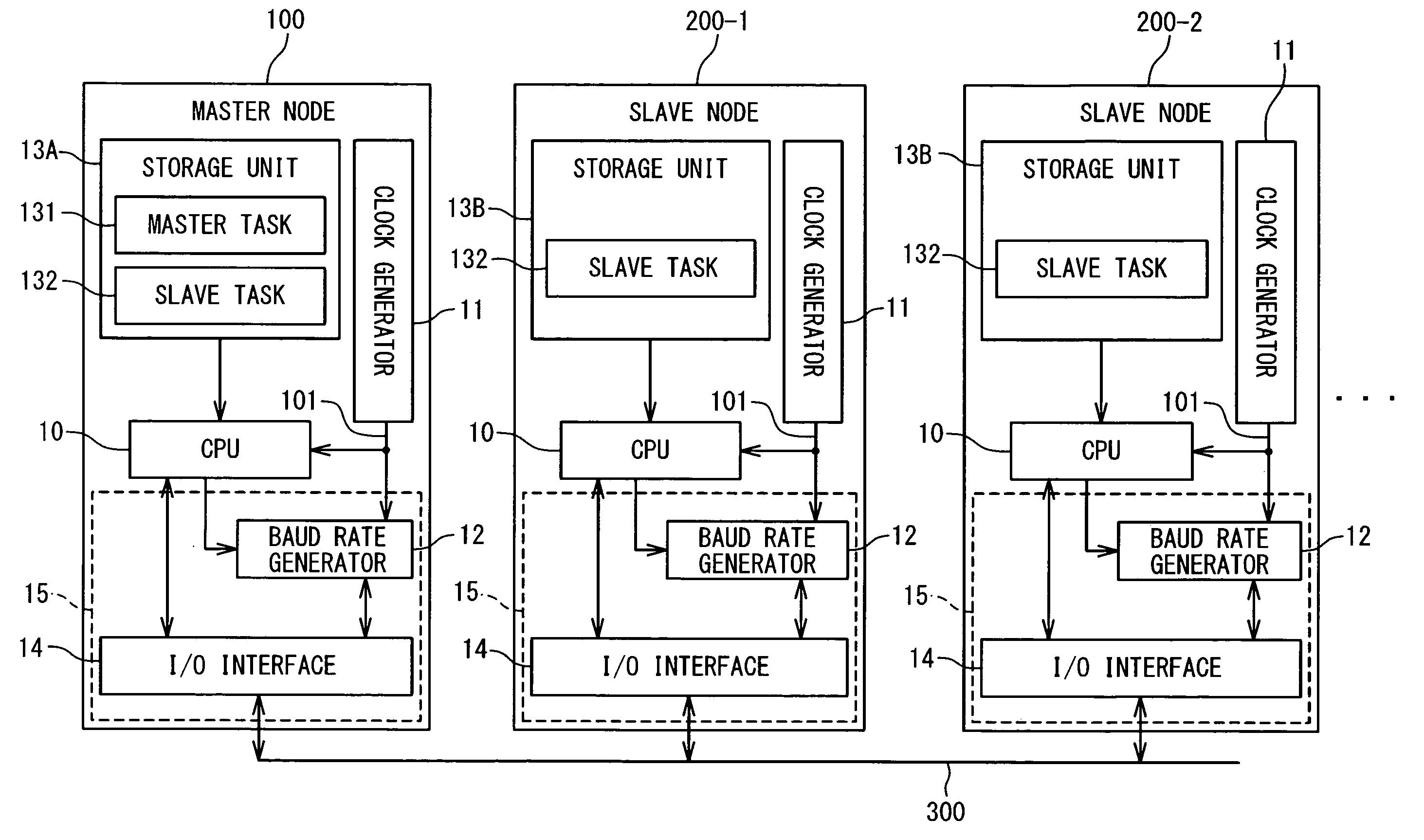
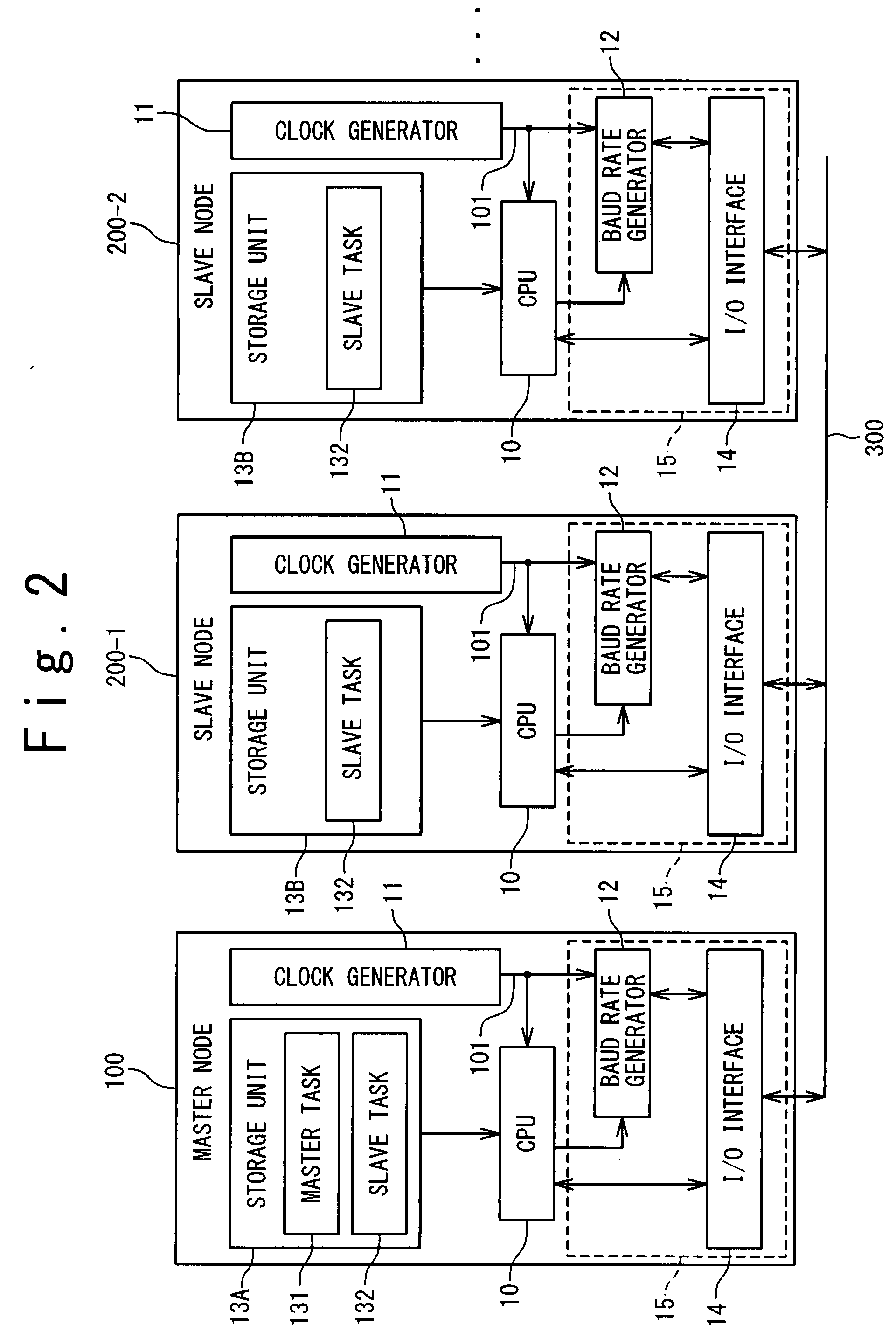
[0063] Next, the serial communication system according to a second embodiment of the present invention will be described with reference to FIGS. 9 and 10. Referring to FIG. 2, the serial communication system according to the second embodiment includes a baud rate generator 12B as the baud rate generator 12. The description of the configuration and operation of components having the same reference numerals as those of the first embodiment will be omitted.
[0064]FIG. 9 is a block diagram showing the configuration of the baud rate generator 12B according to the second embodiment. Referring to FIG. 9, the baud rate generator 12B of the second embodiment includes a baud rate correcting circuit 24B, instead of the baud rate correcting circuit 24A of the first embodiment. FIG. 10 is a block diagram showing the configuration of the baud rate correcting circuit 24B of the second embodiment. Referring to FIG. 10, the baud rate correcting circuit 24B of the second embodiment includes a correct...
third embodiment
[0074] Next, the serial communication system according to a third embodiment of the present invention will be described with reference to FIGS. 11 and 12. Referring to FIG. 2, the serial communication system according to the third embodiment includes a baud rate generator 12C as the baud generator 12. The description of the configuration and operation of the components having the same reference numerals as those of the first and second embodiments will be omitted.
[0075]FIG. 11 is a block diagram showing the configuration of the baud rate generator 12C according to the third embodiment. Referring to FIG. 11, the baud rate generator 12C of the third embodiment includes a baud rate correcting circuit 24C instead of the baud rate correcting circuit 24A of the first embodiment. Further, the baud rate set value 35 is supplied to the baud rate correcting circuit 24C of the present embodiment from the baud rate initial value setting register 26.
[0076]FIG. 12 is a block diagram showing the...
PUM
 Abstract
Description
Claims
Application Information
 - R&D
- Intellectual Property
- Life Sciences
- Materials
- Tech Scout
- Unparalleled Data Quality
- Higher Quality Content
- 60% Fewer Hallucinations
Browse by: Latest US Patents, China's latest patents, Technical Efficacy Thesaurus, Application Domain, Technology Topic, Popular Technical Reports.
© 2025 PatSnap. All rights reserved.Legal|Privacy policy|Modern Slavery Act Transparency Statement|Sitemap|About US| Contact US: help@patsnap.com