
Method and Device for Trenchless Laying of Pipelines

a pipeline and trenchless technology, applied in the field of trenchless underground laying of pipelines, can solve the problems of inability to form impermeable zones or filter cakes, undesired reactions, and inability to achiev

Inactive Publication Date: 2007-12-20
STEIN & PARTNER
View PDF5 Cites 8 Cited by
  • Summary
  • Abstract
  • Description
  • Claims
  • Application Information

AI Technical Summary

Benefits of technology

[0020] The present invention describes a method and a device for trenchless underground laying of pipelines, in which, from a starting shaft, a shield tunnel boring machine and pipes following the latter are driven through the ground, the shield tunnel boring machine producing a borehole, the diameter of which is slightly larger than the outer diameter of the pipes and the annular space existing between the borehole wall and the pipes being filled with a supporting and lubricating agent, with which suddenly occurring supporting and lubricating agent losses or pressure drops due to soil regions of a different condition can be avoided.
[0021] As a result of the fact that, during the advance, at least in the region of the shield tunnel boring machine or of the first pipe following the shield tunnel boring machine or of the first lubricating station, a continuous or periodic examination of the condition of the ground is carried out and, dependent upon the result of the examination, the ground in the examined region is sealed and / or solidified by a sealing and / or a solidifying medium and / or the composition of the supporting and lubricating agent is adjusted, the ground can be prepared by the sealing and / or solidifying medium such that it has sufficient density and stability for the prepared supporting and lubricating agent, or, by corresponding adjustment of the composition of the supporting and lubricating agent, this can be adapted during the pipe advance to the respective ground condition.
[0025] In the annular space, preferably at least two blocking elements (packers) which delimit the annular space in the longitudinal direction of the pipe are provided between the borehole wall on the one hand and the piping on the other hand, which blocking elements can be expanded in the radial direction. It is advantageous that the mutual spacing of the blocking elements can be changed in the longitudinal direction, in particular a front blocking element in the region of the shield tunnel boring machine or of one of the front pipes or of the first lubricating station being disposed moveably with the latter and a rear one being disposed in a stationary manner in the region of the starting shaft. A further blocking element can be provided approximately one pipe length behind the front blocking element, as a result of which the testing chamber is sealed relative to the remaining annular chamber of the already laid piping, so that, in the remaining annular space, the suspension pressure defined for safeguarding the advance can be maintained during the examination.

Problems solved by technology

A problem which occurs frequently in practice is presented by supporting and lubricating agent losses and pressure drops which go beyond a tolerable amount, with significant consequences for the further course of the advance operations as far as advance standstill or impermissible stressing of the pipes.
The formation of impermeable zones or of the filter cake is however only successful when the bentonite particles which are dispersed in the bentonite drilling fluid or bentonite-polymer drilling fluid are larger than the smallest pores in the existing soil or freely occurring polymer particles block any still available pores mechanically-physically as a result of their moveability and plasticity.
The danger exists however hereby that combinations of a plurality of polymers can lead to undesired reactions.
Since, however, all the lubricating stations are supplied with the supporting and lubricating agent via a closed circulation from a single container or mixer installed in the region of the starting shaft, it is not possible, along the advance route, to react at the individual lubricating stations to changing geological structures with different supporting and lubricating agents which are suitable for the respective application case.
c) In loose, pebbly soils, the danger exists furthermore that the annular gap being dug collapses directly behind the shield tail over the piping.
In this case there are no possibilities for producing the annular gap again.
There should be mentioned as disadvantages of this technology, which stand in the way of wider use, a very complex construction of shield tail and trailer, relatively large spatial requirement for the tube magazine and also the risk of damage to the tube.

Method used


Image

  • Method and Device for Trenchless Laying of Pipelines
  • Method and Device for Trenchless Laying of Pipelines

Examples


Embodiment Construction

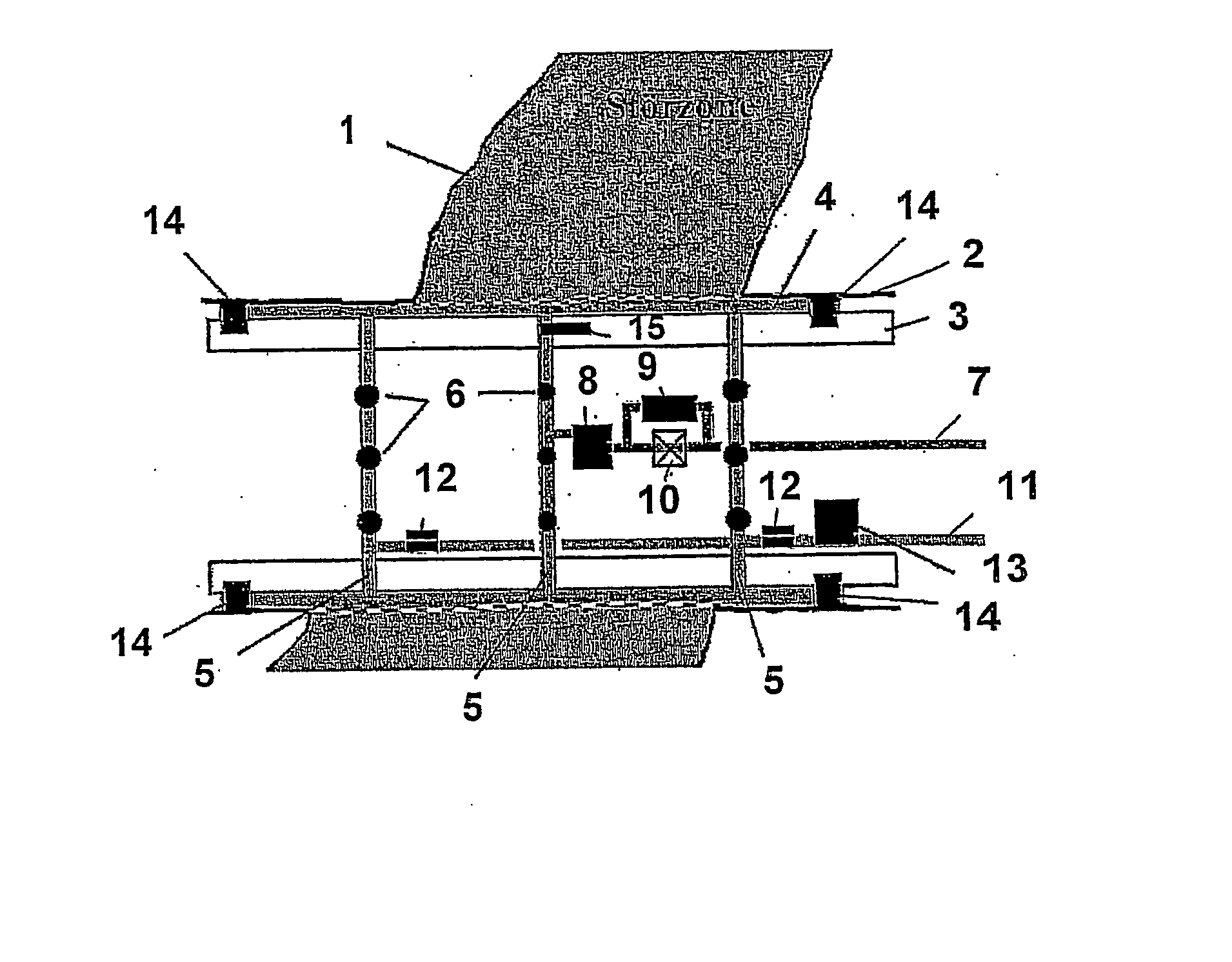
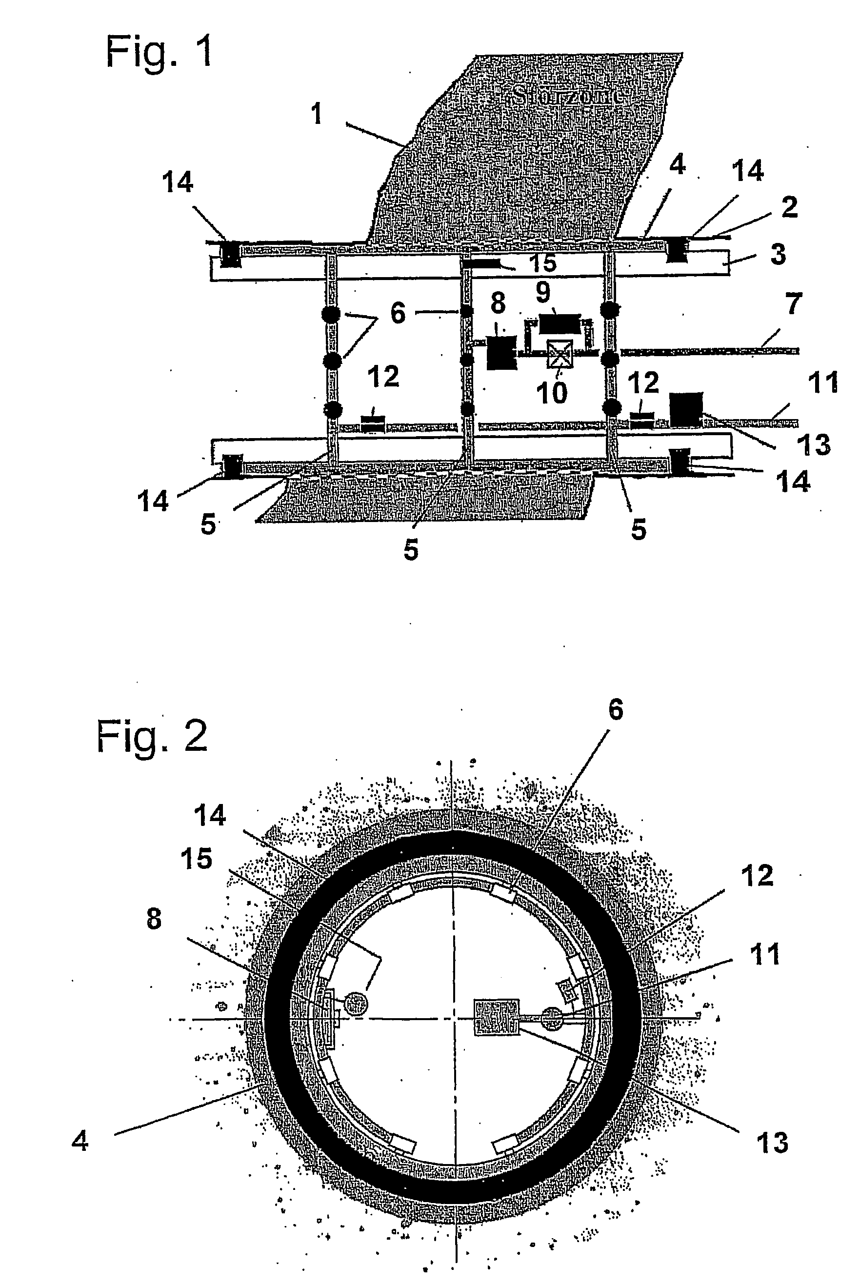
[0029]FIGS. 1 and 2 show a borehole 2 which is surrounded by the ground 1 and into which piping comprising individual pipes is introduced. The borehole 2 is produced by a shield tunnel boring machine which is disposed in front of (in FIG. 1 on the left-hand side) the piping and advanced in the forward direction (in FIG. 1 to the left), an annular space 4 being maintained between the wall of the borehole 2 and the individual pipes 3. A trailing pipe can be provided if necessary between the shield tunnel boring machine and the first of the following pipes 3.

[0030] The illustrated pipe 3, which is for example the first pipe behind the shield tunnel boring machine or at the first lubricating station, contains a test and injection device with three annular injection lines 5 which abut on the inner wall of the pipe 3 and, in the circumferential direction at uniform mutual spacings, have injection connection pipes 6 which are guided radially through borings in the pipe 3 and discharge int...


PUM


Abstract

Described is a method for the trenchless underground laying of pipes. According to said method, a shield tunnel boring machine and then subsequently pipes are driven through the ground starting from a starting shaft. The shield tunnel boring machine produces a borehole whose diameter is slightly greater than the outer diameter of the pipes. The annular space between the borehole wall and the pipes thereby obtained is filled with a supporting and lubricating agent. During advance, a continuous and periodical examination of the composition of the ground is carried out in the area of the shield tunnel boring machine or the first pipe following the shield tunnel boring machine or the first lubricating point. Depending on the result of the examination, the ground in the examined area is sealed off and / or solidified by a sealing and / or solidifying agent and / or the composition of the supporting and lubricating agent is adjusted.

Description

FIELD OF THE INVENTION [0001] The present invention relates to a method for trenchless underground laying of pipelines and also to a device for implementing this method. BACKGROUND INFORMATION [0002] In the laying of supply and waste pipes above all in areas within towns, technical and economic requirements resulting from the presence of sensitive living spaces, dense mains systems and much used highways have led to the fact that the closed construction method relative to the open construction method is continually gaining in importance. Pipe advance counts amongst the most important construction methods in this respect for trenchless laying of sewers, water pipes, protected and jacketed tubes, ducts and conduits. [0003] In this method, advance pipes are driven through the subsoil into a target shaft starting from a starting trench with the help of a main pressing station and assistance of intermediate pressing stations. The advance in straight or curved line guidance is thereby mad...

Claims


Application Information

Patent Timeline
Patent Type & Authority Applications(United States)
IPC IPC(8): E21B7/20E21C39/00
CPCE21C39/00E21B7/20
Inventor STEIN, DIETRICH
Owner STEIN & PARTNER
Learn More