[0014] An aspect of some embodiments of the invention relates to methods for creating electrical and mechanical contacts between electrical components, having located thereon electrical pads, using a conductive material, such as
adhesive, while avoiding the risk of creating lateral conductance between the pads. In an exemplary embodiment of the invention, the electrical pads are located on polymeric /
heat sensitive substrates, such as PET foils, as well as brittle components, such as PCBs. In some exemplary embodiments of the invention, at least one non-conductive spacer is used to avoid creating lateral conductance between the pads. Optionally, the non-conductive spacer is located on a PCB. Optionally, the non-conductive spacer is located on a sensor. Optionally, a conductive adhesive is applied to the pads subsequent to the placement of the non-conductive spacer. The spacer is operative, in some embodiments of the invention, to act as a blocking element to stop lateral flow of the conductive
epoxy.
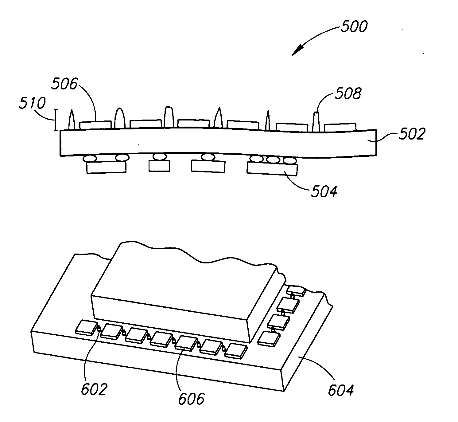
[0015] In some exemplary embodiments of the invention, a conductive spacer is used as part of the
contact mechanism, avoiding any lateral conductance between the pads. Optionally, at least one conductive spacer is placed on a pad. Since for use as a spacer, the conductive spacer is required to be coherent and, when conductive
epoxy is used, should be cured before
assembly, optionally a supplemental
coating of a conductive adhesive is placed on the conductive spacer prior to assembly. Since the spacer is conductive and forms part of the contact, only a small amount of
epoxy is used, making it easier to avoid lateral flow to the next spacer.
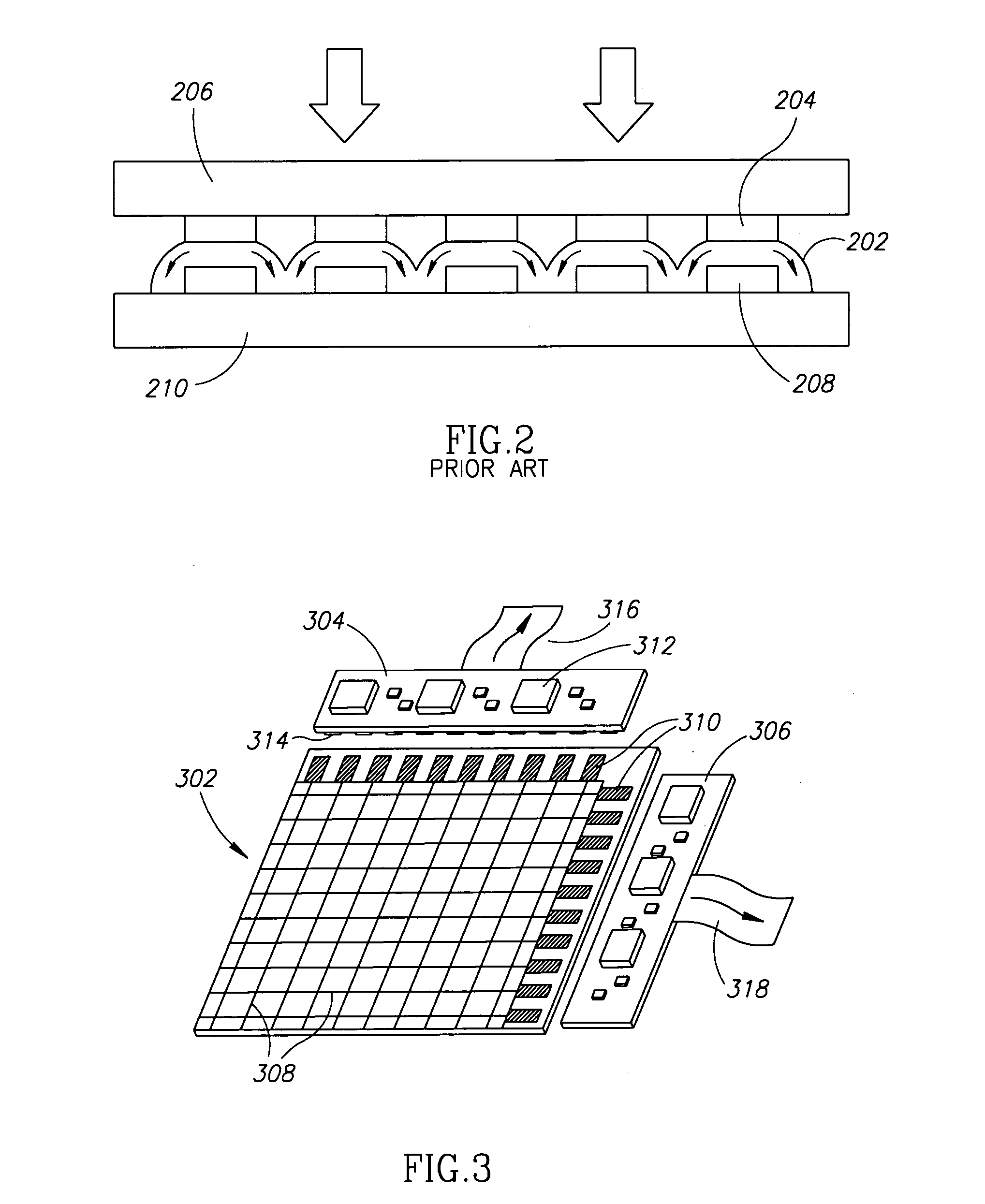
[0017] An aspect of some exemplary embodiments of the invention relates to methods of manufacturing a sensor assembly. Optionally, the sensor assembly is a component of a digitizer, a
personal computer, a personal data assistant or a
mobile phone. In an exemplary embodiment of the invention, a
sensor array and at least one PCB are connected together electrically and / or mechanically while avoiding creating lateral conductance between electrical pads located thereon. In an exemplary embodiment of the invention, the connected
sensor array and at least one PCB are secured within a frame. Optionally, the frame provides
mechanical stability to the sensor assembly. Optionally, the frame provides a recess for locating a
peripheral coil. In some exemplary embodiments of the invention, the frame is provided with alignment extensions to assist with aligning the frame with another object, such as an LCD screen. In an exemplary embodiment of the invention, a
peripheral coil is placed within the recess of the frame. Optionally, the
peripheral coil is constructed of a conductive material, such as
copper. Optionally, the peripheral coil is wound about the frame in order to position it within the recess. Optionally, one end of the peripheral coil is connected to a first set of electrical pads and a second end of the peripheral coil is connected to a second set of electrical pads. In an exemplary embodiment of the invention, the
sensor array, PCB, frame and peripheral coil are encapsulated in a non-conductive material to improve the
mechanical stability of the assembly and to help secure the peripheral coil in place.
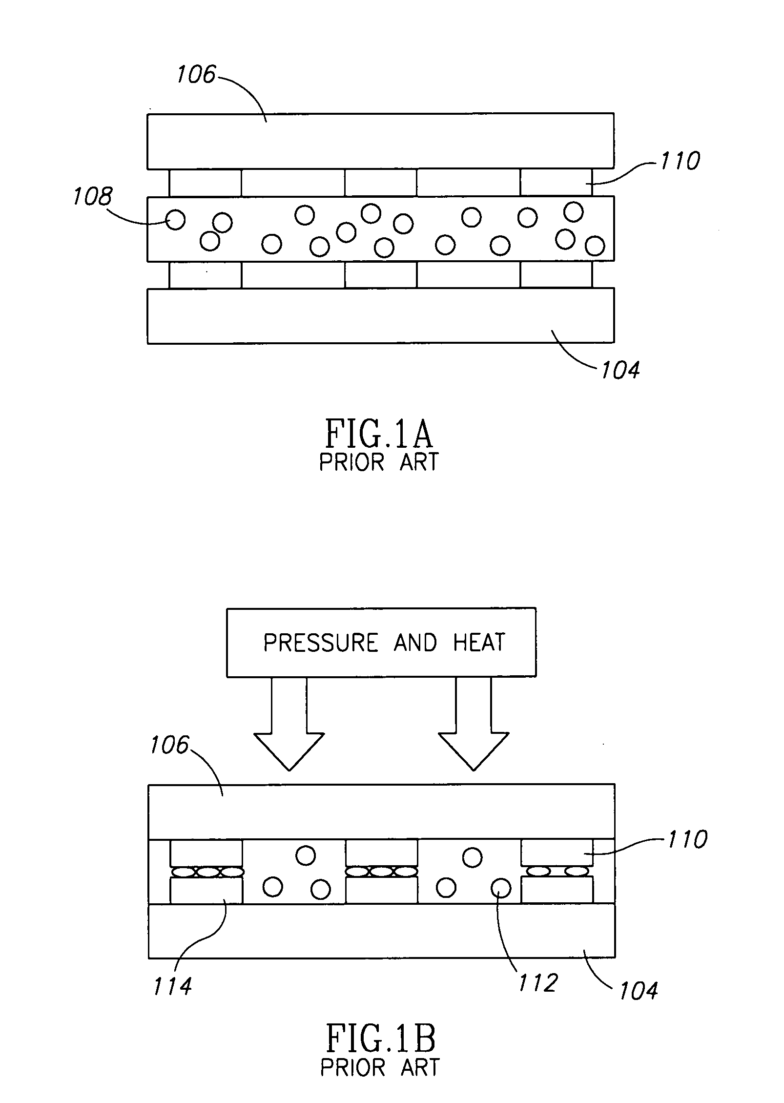
[0018] There is thus provided in accordance with an exemplary embodiment of the invention, a method for connecting substrates having electrical conductive elements thereon, comprising: providing at least one spacer between the substrates; applying a conductive material to at least one of the electrical conductive elements; aligning the electrical conductive elements; and, connecting the substrates by urging them together, wherein the at least one spacer prevents lateral spreading of the conductive material on the substrates from bridging a distance between adjacent conductive elements during the connecting. In some exemplary embodiments of the invention, the method further comprises
filling in gaps between the substrates. Optionally, the gaps are filled in with a non-conductive adhesive. Optionally, at least one of the substrates is a PCB. Optionally, at least one of the substrates is a sensor array. Optionally, at least one spacer is non-conductive. Optionally, at least one spacer is conductive. Optionally, at least some of the conductive spacers are comprised in the conductive elements. Optionally, at least one non-conductive spacer is planar. Optionally, at least one non-conductive spacer is elongate. Optionally, the planar spacer prevents lateral spread by blocking the spread. Optionally, at least one spacer determined a distance between the substrates. In some exemplary embodiments of the invention, at least one conductive spacer is comprised of a cured conductive material. Optionally, the electrical conductive elements are pads. Optionally, urging is performed by a weight. Optionally, the urging planarizes at least one of the substrates by conforming the electrical component to the at least one spacer. In some exemplary embodiments of the invention, the conductive material is a conductive adhesive.

