Method for engineering a control system

a control system and control system technology, applied in the field can solve the problems of limited patents for automation of control system engineering, and achieve the effects of reducing the repetitive re-generation of mostly duplicate information, eliminating keypunch errors, and simplifying estimating

Inactive Publication Date: 2007-12-20
SKOREPA BRADLEY J
View PDF11 Cites 7 Cited by
  • Summary
  • Abstract
  • Description
  • Claims
  • Application Information

AI Technical Summary

Benefits of technology

[0013] The control system application engineering method (“method”) described herein automates the process of engineering a control system. Additionally, the method has the ability to generate the entire controller database excluding the sequence of operations for microprocessor based controllers so featured. This method also simplifies estimating and engineering the installation of control systems by creating a structure that allows engineering decisions about a control system to be related in all presentations of information in the engineering documentation. By relating the information in all types of presentations within the engineering documentation, repetitive re-gener

Problems solved by technology

Previous patents automating the engineering of control systems have been limited to ne

Method used


Image

  • Method for engineering a control system
  • Method for engineering a control system
  • Method for engineering a control system

Examples


Embodiment Construction

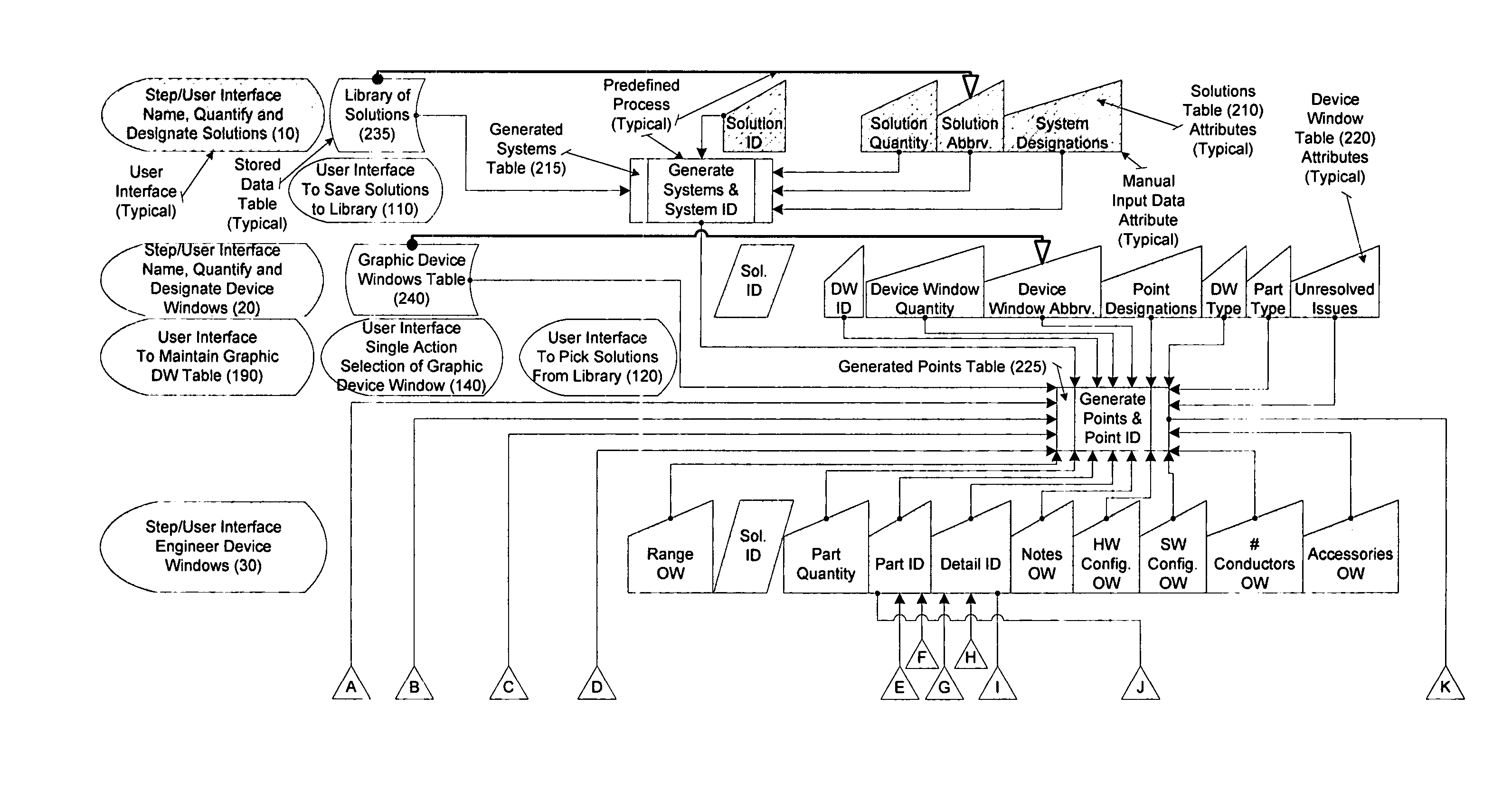
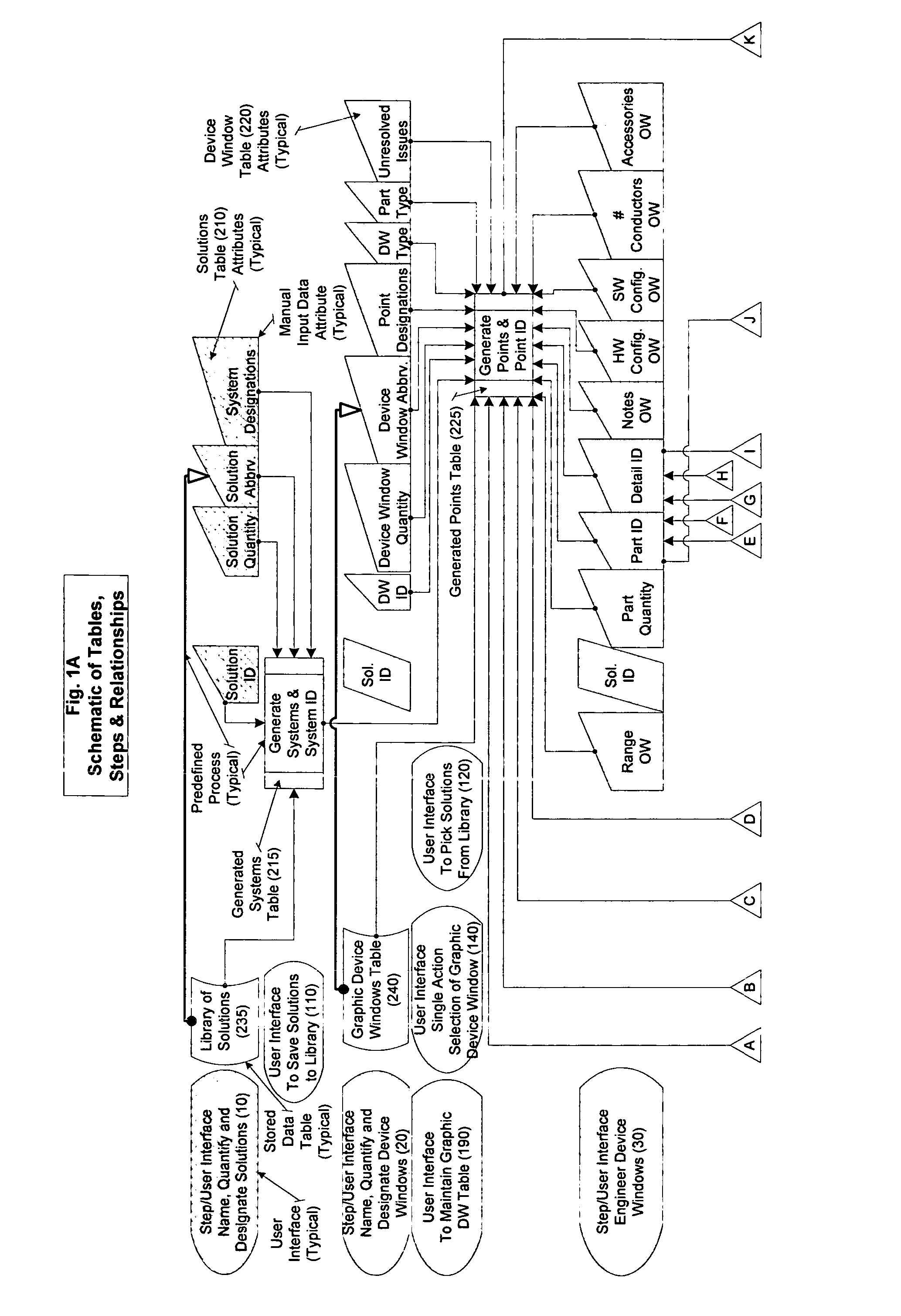
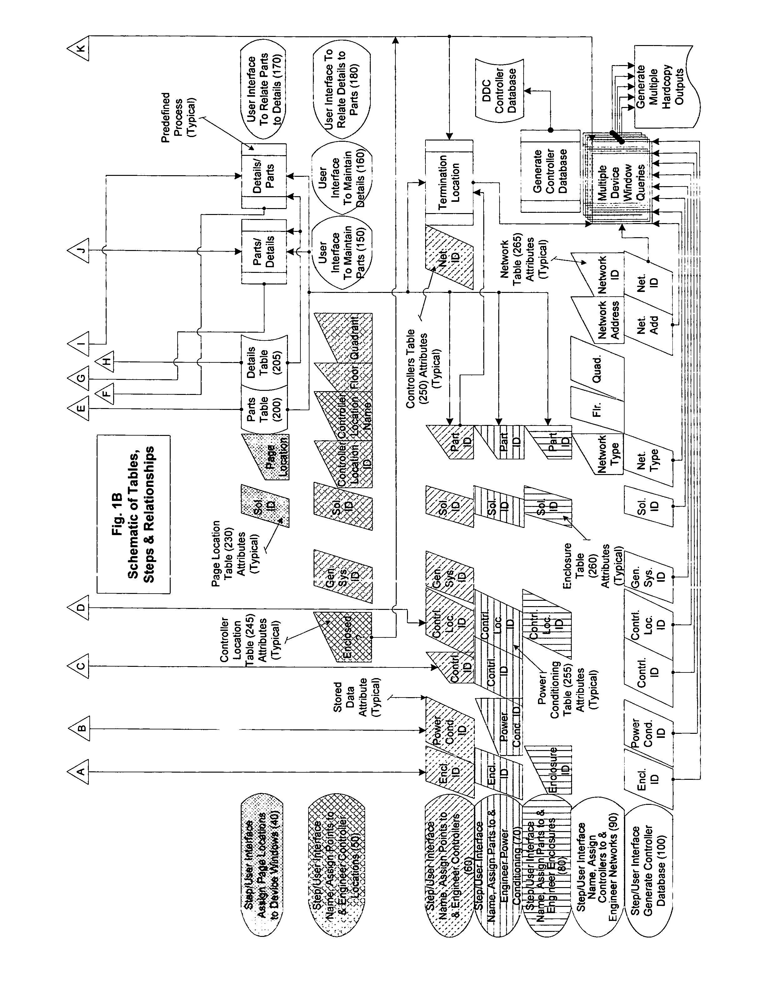
[0020] The control system application engineering method is the structure of the database, the preprogrammed computer commands managing the relationships between tables within the database and the defined iterative engineer steps in the software (User Interfaces) used to populate the database. The iterative steps, schematic representation of the tables and schematic relationships among the tables are summarized in FIGS. 1A & 1B. The attribute “TABLE Name” and all of the attributes that could be attributed to the Part or Details Tables have been omitted from each table representation in FIGS. 1A & 1B to allow room. The Tablcs in the computer database closely duplicate the iterative engineer steps used to populate the database. The tables in the computer database are the Previously Designed Device Parts Table (“Parts Table (200)”), a Previously Defined Details Table (“Details Table (205)”), Solutions Table (210), Generated Systems Table (215), a Device Window Table (220), Generated Po...


PUM


Abstract

The present method is a method to automate the repeatible process of application engineering microprocessor based control systems and creating the related documentation to submit for engineer approval and construct the control system. Prior to this method engineering every decision about point assignment, part selection, controller addressing et al was either made and only recorded upon the engineering documents or made in the field and either recorded manually or not at all. As the result when those engineering decisions were required elsewhere in the engineering documents individuals could only refer to those documents when retabulating the information. The present method allows a user to record all most all of the engineering decisions in a soft environment allowing the decisions to be repeatably used in every engineer document. As the result efficiency in the task of application engineering is increased and errors created as information is transferred are eliminated.

Description

[0001] This application is based upon and claims priority from U.S. provisional application Ser. No. 60 / 696,935, which is incorporated herein by reference.BACKGROUND OF THE METHOD [0002] 1. Field of the Method [0003] Applicants' method relates to a method for engineering a control system. More particularly, it relates to a software application that provides for automating the engineering of a control system. [0004] 2. Background Information [0005] A control loop must include a sensor (an input point), a set-point, a controller and a controlled device (an output point). This definition allows the creation of a computer based automated process for engineering a system of control loops (a control system). Currently when engineering a control system comprised of off-the-shelf components, system control requirements are generated by identifying and defining input and output points (points), controllers and enclosures (an enclosed housing into which the controller, power conditioning and ...

Claims


Application Information

Patent Timeline
IPC IPC(8): G06F19/00
CPCG05B19/042G05B2219/35494G05B2219/23009G05B2219/23008
Inventor SKOREPA, BRADLEY J.
Owner SKOREPA BRADLEY J
Why Eureka
Try Eureka