Modular boat lift canopy assembly and kit

a module and canopy technology, applied in the field oftruss type framework canopies, can solve the problems of inability to easily adapt to the construction of canopy kits by unskilled users, inconvenient use, and high cost of canopy kits, and achieve the effects of simple adjustment of canopy overhang or length, easy construction, and simple adjustment of canopy position

Inactive Publication Date: 2007-12-27
IPO
View PDF10 Cites 23 Cited by
  • Summary
  • Abstract
  • Description
  • Claims
  • Application Information

AI Technical Summary

Benefits of technology

[0014] The present invention is a boat lift canopy, comprising a truss type framework with a base frame that may be rectangular, comprised of side and end horizontal members. The framework is comprised of channel-ridge interlocking extruded components, enabling easy construction with minimal or no welded parts. Joined to the base frame and circumscribed by it is a tie bar frame, which may be discontinuous. A fabric cover, which in preferred embodiments is decorative as well as functional, snugly encloses the outside of the framework, wraps around the base frame and is secured to the tie tube frame with canopy ties. The boat lift canopy is held above the boat lift by vertical members, which in some embodiments are vertical extensions

Problems solved by technology

While boat houses can provide such shelter, they are expensive and often impractical.
The large number of welded connections in a typical prior art canopy presents risk of metal fatigue and fracture at welded stress points, leading to structural failure.
Prior art canopy design does not lend itself easily to canopy construction from a kit by unskilled users.
A further limitation of the prior art boat lift canopy is that it is often desirable to change the length of a canopy, as when, for example, the lift is used for a boats of a different length.
As is clear from the foregoing description, however, the prior art canopy is not ea

Method used


Image

  • Modular boat lift canopy assembly and kit
  • Modular boat lift canopy assembly and kit
  • Modular boat lift canopy assembly and kit

Examples


Embodiment Construction

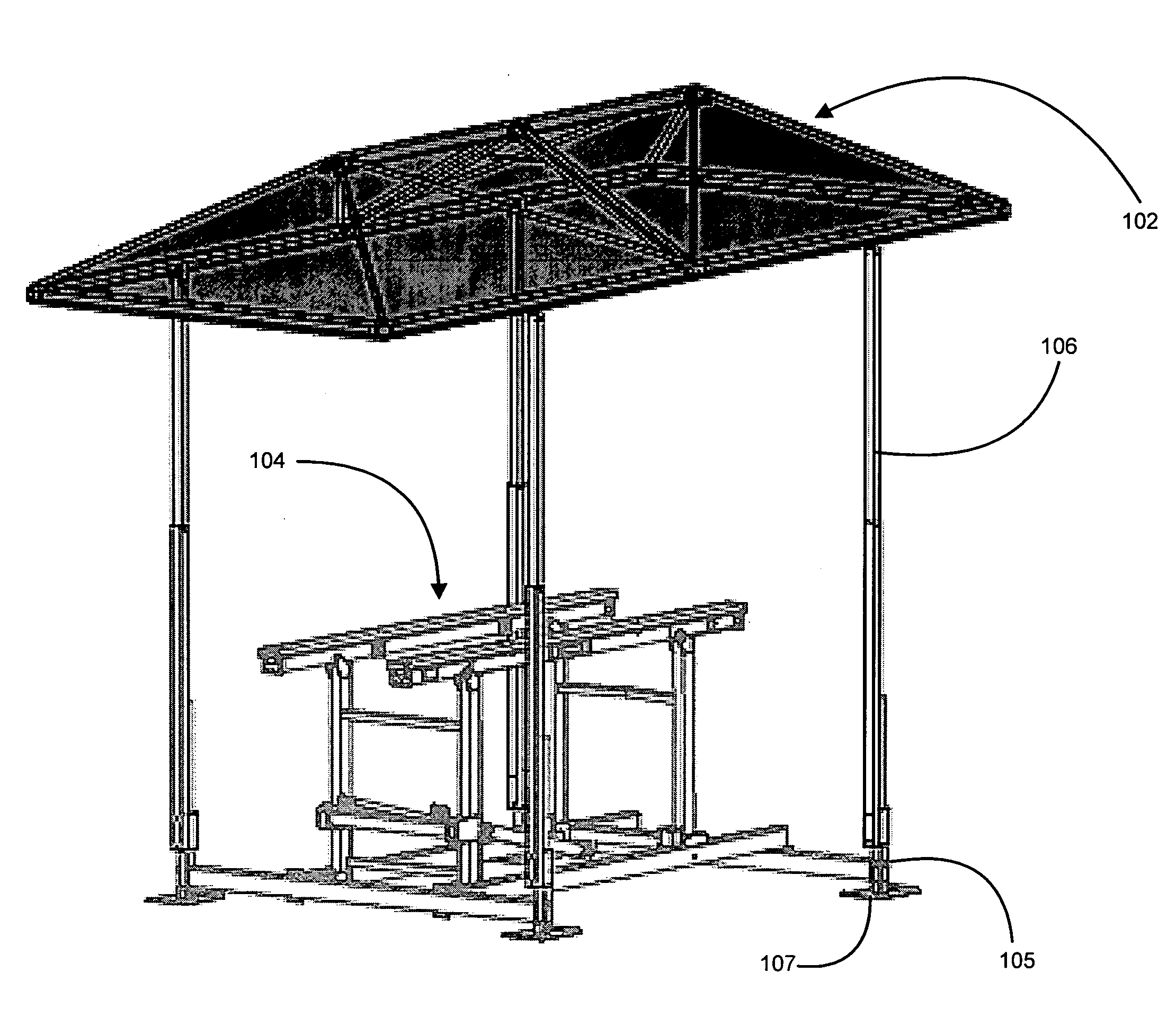
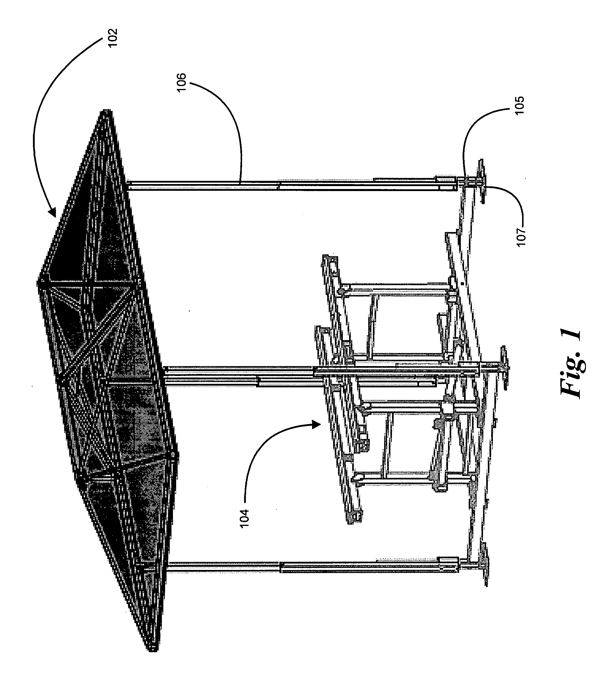
[0028] Turning now to FIG. 1, depicted is an embodiment of the present invention. Canopy 102 is constructed as a truss type framework over which is wrapped a canvas cover. Canopy 102 supports its canvas cover over a watercraft lift 104, standing upon upright members 106, the canopy configured to sit upon legs 105 terminating in feet 107. Lift 104 may be any form of watercraft lift designed to be affixed to the bottom of a body of water, such as described in U.S. Pat. No. 5,908,264 to Hey or U.S. Pat. No. 5,184,914, issued to the inventor of the present invention and which is incorporated herein by reference. Alternatively, lift 104 may be a floating lift as described in U.S. Pat. No. 5,485,798 to Samoian et al., or U.S. patent application Ser. No. 10 / 816,992 by the inventor of the present invention, incorporated herein by reference. Legs 105 may be dedicated to canopy 102, or in the alternative legs 105 may serve as supports for both canopy 102 and lift 102.

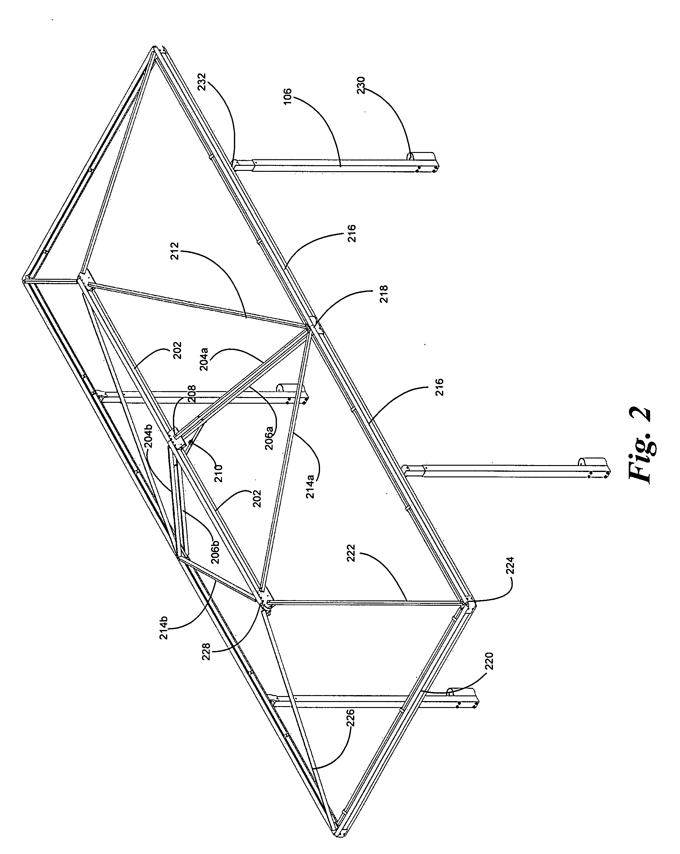
[0029] Turning now to FI...


PUM


Abstract

A boat lift canopy comprises a truss type framework with a base frame that may be rectangular, comprised of side and end horizontal members. The framework is comprised of channel-ridge interlocking extruded components, enabling easy construction with minimal or no welded parts. Joined to the base frame and circumscribed by it is a tie bar frame, which may be discontinuous. A fabric cover snugly encloses the outside of the framework, wrapping around the base frame and secured to the tie tube frame with canopy ties. The boat lift canopy is held above the boat lift by vertical members connecting to supporting legs. The canopy is releasably coupled to the vertical members at the tie tube frame, facilitating adjustable extension of canopy overhang or length by the addition of frame members extending the canopy framework. The framework of the canopy employs a truss design such as Howe kingpost to maximize framework strength to support substantial cantilevered canopy overhangs. Modular, easily assembled components enable provision of the canopy as a kit of components for user assembly.

Description

CROSS-REFERENCE TO RELATED APPLICATION [0001] This application is a continuation-in-part of a previous application by the inventor of the present invention, U.S. patent application Ser. No. 10 / 845,372, titled “Boat Lift Canopy Assembly”, filed in the United States Patent and Trademark Office on May 13, 2004.BACKGROUND OF THE INVENTION [0002] 1. Field of the Invention [0003] This invention relates to truss type framework canopies to provide shelter for boats. More particularly, this invention relates to an improved canopy structure mounted above a boat lift and a kit for assembling such a structure. [0004] 2. Description of the Related Art [0005] Users of watercraft have need to shelter docked boats from the elements. While boat houses can provide such shelter, they are expensive and often impractical. Users of watercraft also have need to lift their watercraft from the water, for example for maintenance or in preparation for land transportation of the watercraft, along with a need t...

Claims


Application Information

Patent Timeline
IPC IPC(8): E04H15/34B63B17/02B63C5/00E04H15/42
CPCB63B17/02E04H15/34B63C5/00E04H15/18E04H15/06E04H15/54
Inventor BASTA, SAMUEL T.
Owner IPO
Why Eureka
Try Eureka