Eureka AIR delivers breakthrough ideas for toughest innovation challenges, trusted by R&D personnel around the world.

Static Exciter System for a Generator and Method of Operation

Active Publication Date: 2007-12-27
GENERAL ELECTRIC TECH GMBH
View PDF11 Cites 22 Cited by
  • Summary
  • Abstract
  • Description
  • Claims
  • Application Information

AI Technical Summary

Benefits of technology

[0010] One of numerous aspects of the present invention includes providing a static exciter system with the capability to briefly increase the excitation (“excitation boosting”), which avoids the disadvantages of known exciter systems and is distinguished by high functional reliability and a simple, space-saving design, and to specify a method for its operation.
[0015] It is advantageous in terms of space requirement, energy density, reliability and installation costs if the capacitor or capacitors is or are in the form of ultracapacitors or supercapacitors having a specific energy density of 1 to 10 Wh / kg.
[0017] If the brief increase in the excitation is intended to be controlled from a central point, it is advantageous if the switch for the connection of the second means can be operated via a receiver, by means of a wire-based signal or a radio signal.

Problems solved by technology

Despite this over-design, problems occur in conventional static exciter systems, for the following reasons: grid-system disturbances are frequently caused by short circuits in the transmission lines.
However, this can be achieved only partially because the voltage which remains during the short circuit and shortly after it does not allow a brief field-current surge to be built up.
Even the ceiling factor that is incorporated cannot ensure adequate excitation in all circumstances during this time period.
In both arrangements, the availability of the generator is adversely affected to a major extent, because complete excitation fails when one of the described components in the arrangements fails.
This can lead to voltage spikes and to a malfunction or damage to the thyristors or the field winding of the generator.

Method used


Image

  • Static Exciter System for a Generator and Method of Operation
  • Static Exciter System for a Generator and Method of Operation
  • Static Exciter System for a Generator and Method of Operation

Examples


Embodiment Construction

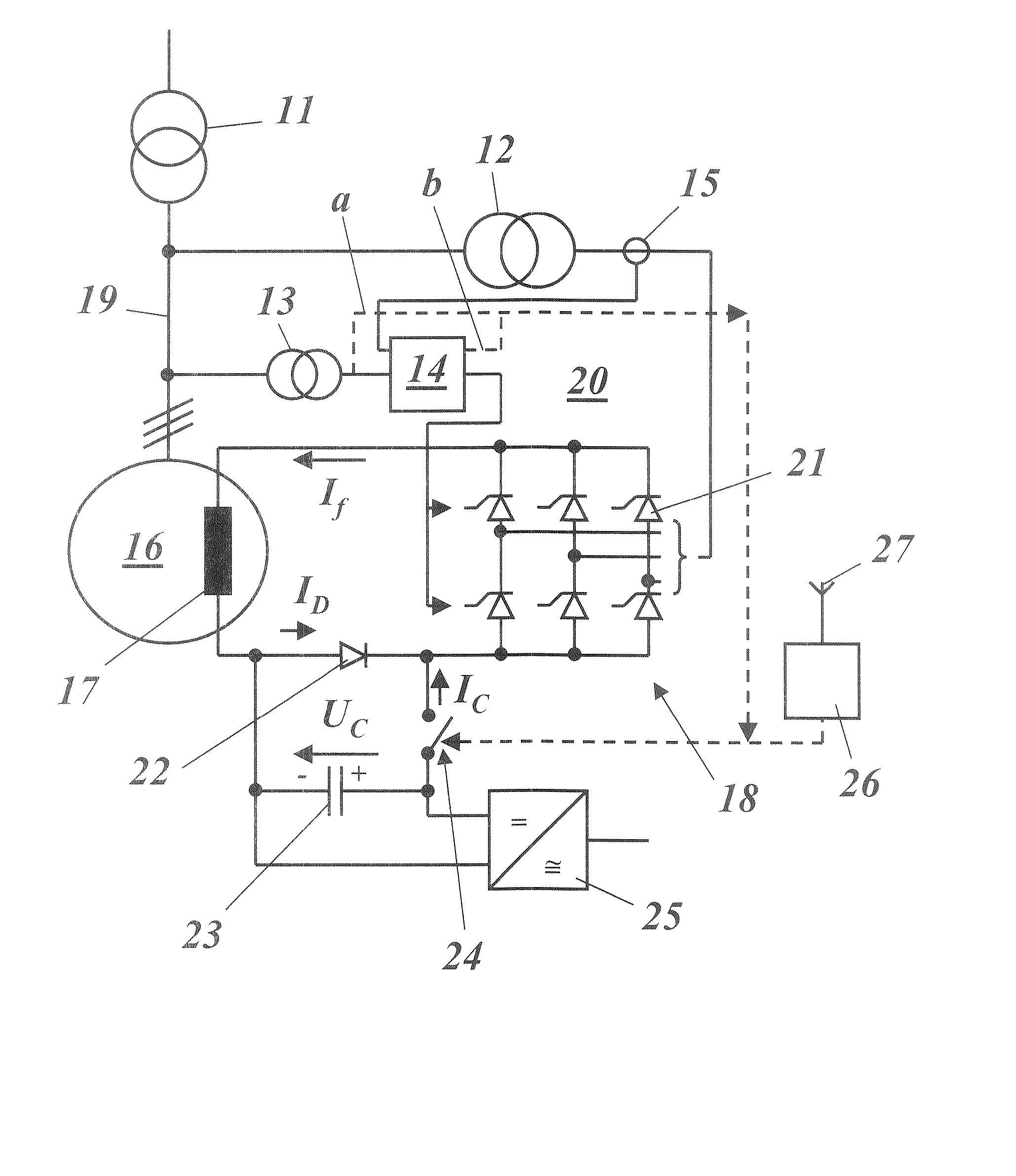
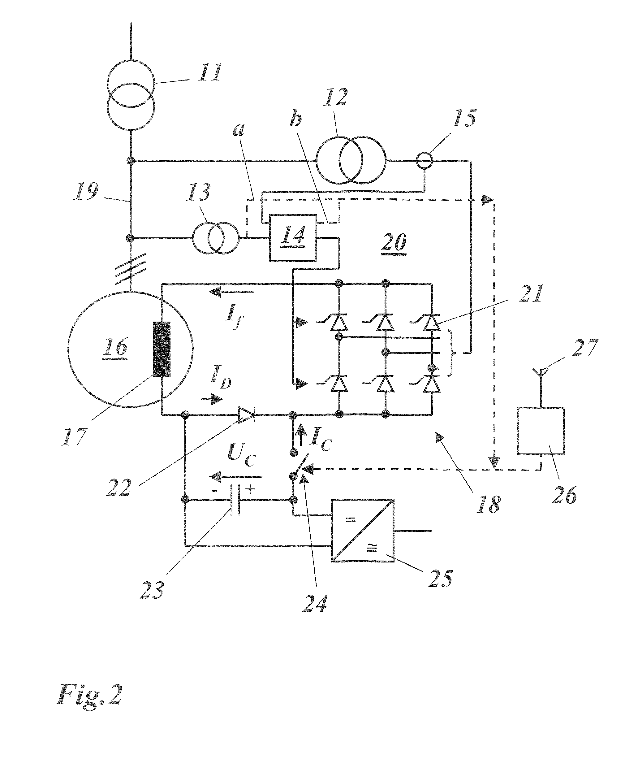
[0026]FIG. 2 shows a simplified circuit diagram of a static exciter system according to a first exemplary embodiment of the invention. This is, once again, based on a generator 16 with a field winding 17, which is connected to a grid system via a busbar 19 and a machine transformer 11. The field winding is supplied with field current If from a static exciter system 20, which essentially includes an exciter transformer 12 followed by a thyristor bridge 18 which is fitted with thyristors 21. The thyristor bridge 18 is driven by an automatic voltage regulator (AVR) 14, which receives as input variables, on the one hand via a voltage transformer 13, the generator voltage applied to the busbar 19 and, on the other hand via a current transformer 15, the current flowing in the exciter system. The output side of the thyristor bridge 18 is connected to the field winding 17 and, together with it, forms an exciter circuit.

[0027] A diode 22 is installed in the forward-bias direction in the exc...


PUM


Abstract

A static exciter system (20) for the field winding (17) of a generator (16) which is connected to a grid system via a busbar (19) includes a first device (12, 18, 21) for production of a DC voltage, which is connected to the field winding (17) and together with the field winding (17) form an exciter circuit, as well as a second device (23; 29, C1, . . . , C3) for emission of electrical energy, which second device (23; 29, C1, . . . , C3) briefly feeds additional energy into the exciter circuit when required. An exciter system such as this results in the capability to briefly increase the excitation in a simple, functionally reliable and space-saving manner, by inserting a forward-biased diode (22) into the exciter circuit, and by the capability to connect the second device (23) to the diode (22), in the reverse-bias direction, in order to feed the energy into the exciter circuit.

Description

[0001] This application is a U.S. National Stage filed under 35 U.S.C. § 371 of International application number PCT / EP2005 / 055231, filed 13 Oct. 2005, which claims priority to Swiss Application number 0178 / 04, filed 28 Oct. 2004.BACKGROUND [0002] 1. Field of Endeavor [0003] The present invention relates to the field of generator technology. It relates in particular to a static exciter system, and to a method for operation of an exciter system such as this. [0004] 2. Brief Description of the Related Art [0005] Static exciter systems for feeding the field winding of a generator are widely used. They are distinguished by their robustness and a short response time. A static exciter system of the known type is shown in FIG. 1. The static exciter system 10 in FIG. 1 is associated with a generator 16, which is connected to a grid system (not shown in FIG. 1) via a (3-phase) busbar 19 and a machine transformer 11. The static exciter system 10 is used to feed the field winding 17 of the gen...

Claims


Application Information

Patent Timeline
IPC IPC(8): H02P9/30G05F1/70H02J1/12
CPCH02P9/30H02P9/14
Inventor JOHO, REINHARD
Owner GENERAL ELECTRIC TECH GMBH
Why Eureka
Eureka Blog
Learn More