Cooling Structure of Superconducting Motor
a superconducting motor and cooling structure technology, applied in the direction of windings, magnetic circuit rotating parts, magnetic circuit shape/form/construction, etc., can solve the problems of difficult formation of long hollow portions through a long rotating shaft, inefficient cooling of the superconducting coil in such a case, and inability to cool the superconducting coil sufficiently. to achieve the effect of enhancing the cooling effect and easy formation of the cooling structur
- Summary
- Abstract
- Description
- Claims
- Application Information
AI Technical Summary
Benefits of technology
Problems solved by technology
Method used
Image
Examples
first embodiment
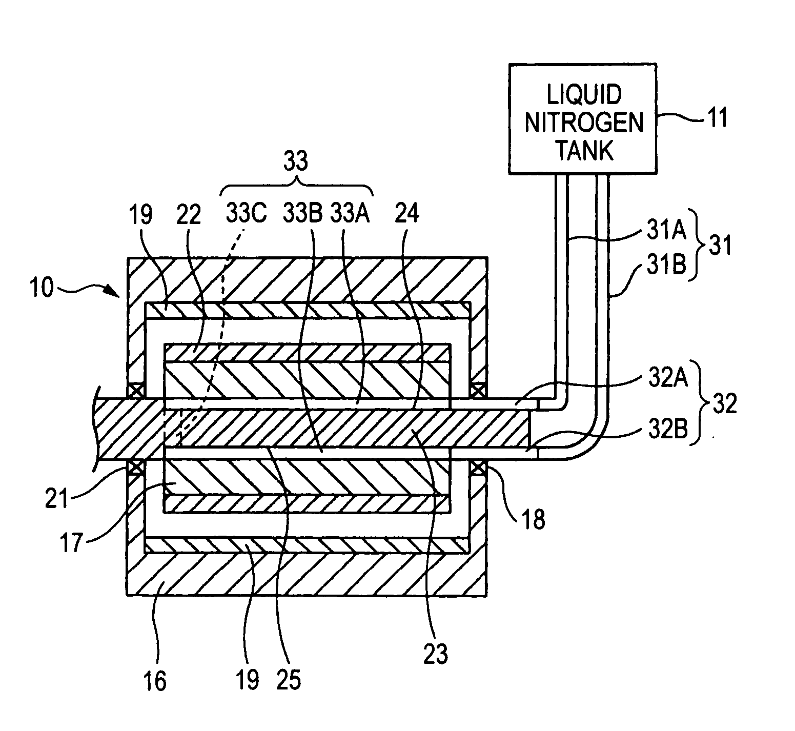
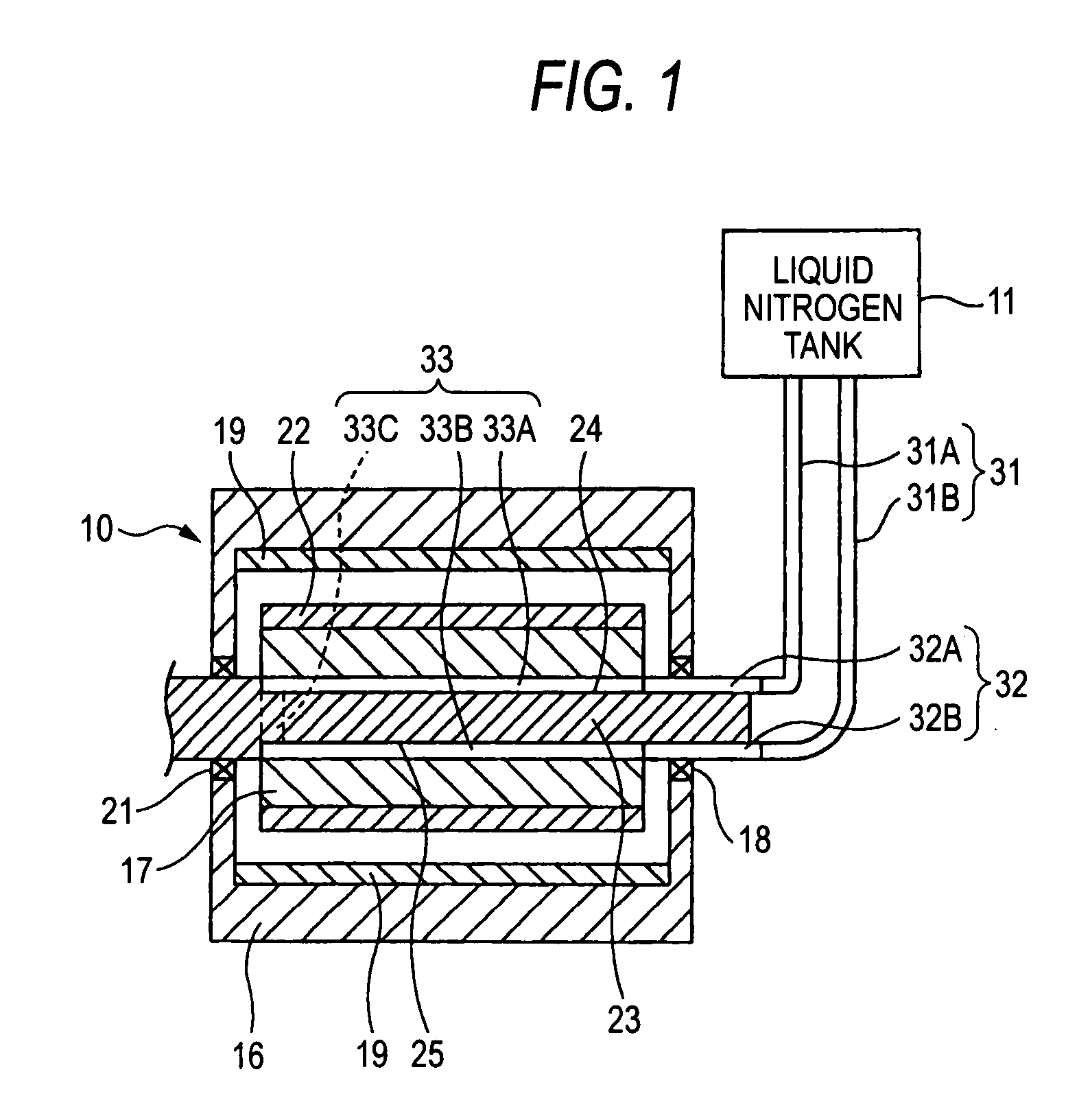
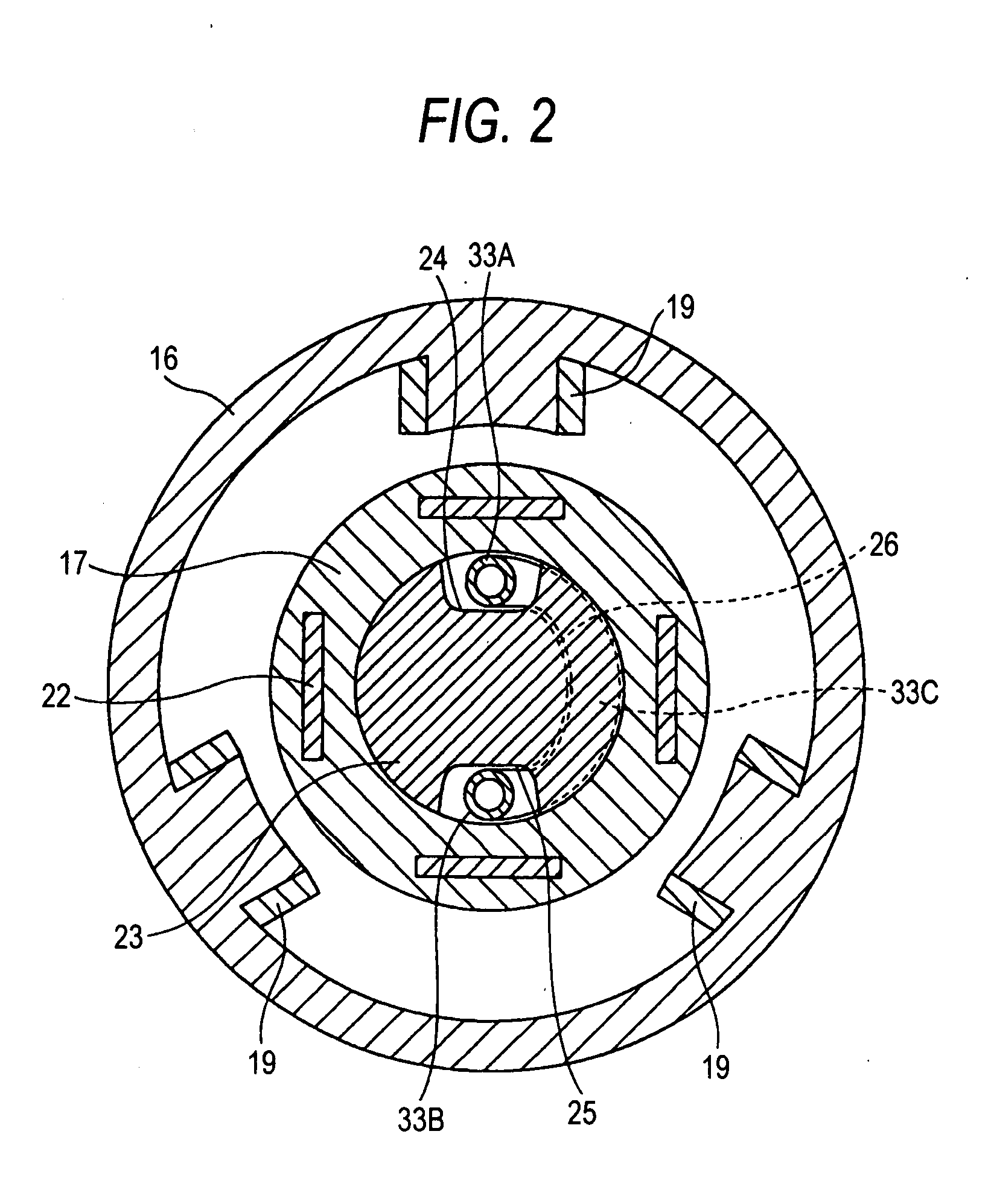
[0066] FIGS. 1 to 4 show the invention. A superconducting motor 10 according to the invention may be used as a propulsion motor of a ship.
[0067] As shown in FIGS. 1 and 2, the superconducting motor 10 includes a stator 16 and a rotor 17 which is rotatably disposed inside a hollow portion of the stator 16, and it is a radial type in which a direction of a magnetic flux of a superconducting coil 22 attached to the rotor 17 is directed in a radial direction.
[0068] The rotor 17 is formed in a cylindrical shape, and may be made of a powder magnetic material. A rotating shaft 23 penetrates through a center of the rotor 17 and is fixed thereto. The rotating shaft 23 extends towards the exterior of the stator 16 through bearings 18 and 21.
[0069] The superconducting coil 22 (or field coil) made of a superconducting material is fixed to the rotor 17. As the superconducting material, bismuth-based or yttrium-based high temperature superconducting materials may be suitably used.
[0070] On the...
second embodiment
[0086]FIGS. 6 and 7 show the invention.
[0087] The difference from the first embodiment is that the second embodiment is a motor of an axial type in which the stators are placed opposite to each other in the axial direction of the rotor, whereby a direction of a magnetic flux of the superconducting coil is directed in the axial direction.
[0088] In a superconducting motor 50 according to this embodiment, a pair of stators 53 and 54 is arranged so as to face each other on respective sides a rotor 52 fixed to a rotating shaft 51 with a predetermined gap being provided the respective sides of the rotor 52.
[0089] The rotor 52 is formed with a through hole 52a at a shaft center portion thereof, and the rotating shaft 51 is inserted through and fixed to the through hole 52a, whereby the rotor 52 and the rotating shaft 51 are corotated.
[0090] Magnetic field element mounting holes 52b are formed on the rotor 52 at intervals in a circumferential direction around the axis thereof. Supercondu...
PUM
 Abstract
Description
Claims
Application Information
 - R&D
- Intellectual Property
- Life Sciences
- Materials
- Tech Scout
- Unparalleled Data Quality
- Higher Quality Content
- 60% Fewer Hallucinations
Browse by: Latest US Patents, China's latest patents, Technical Efficacy Thesaurus, Application Domain, Technology Topic, Popular Technical Reports.
© 2025 PatSnap. All rights reserved.Legal|Privacy policy|Modern Slavery Act Transparency Statement|Sitemap|About US| Contact US: help@patsnap.com


