Discharge Lamp Ballast Device and Lighting Appliance

a discharge lamp and ballast technology, applied in the direction of electric variable regulation, process and machine control, instruments, etc., can solve the problems of excessive load power, failure of the discharge lamp ballast device, and excessive stress on circuit components, so as to achieve stable lighting operation and free from undue stress

Inactive Publication Date: 2007-12-27
MATSUSHITA ELECTRIC WORKS LTD
View PDF5 Cites 20 Cited by
  • Summary
  • Abstract
  • Description
  • Claims
  • Application Information

AI Technical Summary

Benefits of technology

[0007] In view of the above problem, the present invention ahs been achieved to provide a discharge lamp ballast device which is capable of assuring a stable lighting operation free from being reset even upon instantaneous lowering of an input voltage to the inverter immediately after the lamp start, and therefore free from undue stress on the circuit components.
[0010] Accordingly, the reset means is invalidated until the lamp proceeds to the lighting mode after the lamp start. Whereby, even if the output voltage from the chopper to the inverter is instantaneously lowered, the lamp can proceed to the lighting mode without returning to the starting mode or the preheating mode, thereby protecting the circuit components from undue stress. Further, since the inverter stop means is enabled before the expiration of the period in which the reset means is kept disabled, the inverter can be immediately stopped when the lamp abnormality is detected just after the lamp start for protection of the inverter circuit. Particularly, since the frequency sweep means is used to give a transition period during which the switching frequency varies gradually from the starting frequency to the lighting frequency, it is possible to restrain the variation of the chopper output being fed to the inverter during this transition period, thereby assuring a stable transition from the starting mode to the lighting mode.
[0013] The lamp abnormality detection circuit is configured to detect a physical amount indicative of a condition of the discharge lamp, while the inverter stop means is configured to include a signal generation circuit which provides a stop signal when the physical amount exceeds a predetermined reference so that the inverter controller stops the output of the inverter in response to the stop signal. The signal generation circuit is configured to define the reference by a first lamp threshold or a second lamp threshold greater than the first lamp threshold, and to select the second lamp threshold during the transition period (t3−t4) during which the switching frequency varies from the starting frequency to the lighting frequency, and otherwise select the first lamp threshold. Even if the output voltage from the chopper to the inverter is instantaneously lowered during this transition period, the lamp is kept turned on since the reset means is disabled, but the lamp voltage might instantaneously rise above the first lamp threshold due to the lowering of the output current from the inverter. However, since the second lamp threshold higher than the first lamp threshold is relied upon in the transition period for detection of the lamp abnormality, the inverter can be protected from being accidentally stopped in response to a false abnormality detection.
[0014] The inverter stop means is preferred to detect the lamp abnormality based upon a peak value of the voltage across the discharge lamp, and a DC component in that voltage. In this instance, the lamp abnormality detection circuit is configured to include a peak detection circuit for detection of the peak value of the voltage across the discharge lamp, and a DC component detection circuit for detection of the DC component included in the lamp voltage across the discharge lamp. The inverter stop means comprises a first signal generation circuit generating a first stop signal when the peak value exceeds a predetermined threshold, and a second signal generation circuit generating a second stop signal when the DC component exceeds a predetermined threshold, so as to provide the stop signal to the inverter controller for lowering the output of the inverter upon receiving any one of the first and second stop signals. At least one of the first and second signal generation circuits has a first threshold and a second threshold greater than the first threshold, and selects the second threshold during the transition period (t3 to t4) where the switching frequency varies from said starting frequency to the lighting frequency, and otherwise selects the first threshold. With this arrangement, the lamp abnormality can be accurately judged by use of the peak value of the lamp voltage and its DC component, avoiding false detection of lamp abnormality during the transition period.
[0016] Further, the timer includes a circuit for charging and discharging the capacitor externally connected to the integrated circuit so as to determine the end of the preheating mode as well as the starting mode based upon the charged voltage of the capacitor such that the frequency setting section of the frequency sweep means sweeps the frequency in accordance with the variation of the voltage across the capacitor for determining the start of the individual modes. Thus, the capacitor is shared by the timer and the frequency sweep means for reducing a number of components externally connected to the integrated circuit.

Problems solved by technology

However, when the discharge lamp comes to its near lamp-life end, it is likely that the high lamp voltage results in an excessive load power which lowers the output voltage from the chopper to the inverter.
With this consequence, the reset means operates immediately after the lamp start to resume the preheating mode or starting mode, and therefore repeat the preheating mode and the starting mode, thereby giving an excessive stress to the circuit components, and even resulting in a failure of the discharge lamp ballast device.

Method used


Image

  • Discharge Lamp Ballast Device and Lighting Appliance
  • Discharge Lamp Ballast Device and Lighting Appliance
  • Discharge Lamp Ballast Device and Lighting Appliance

Examples


first embodiment

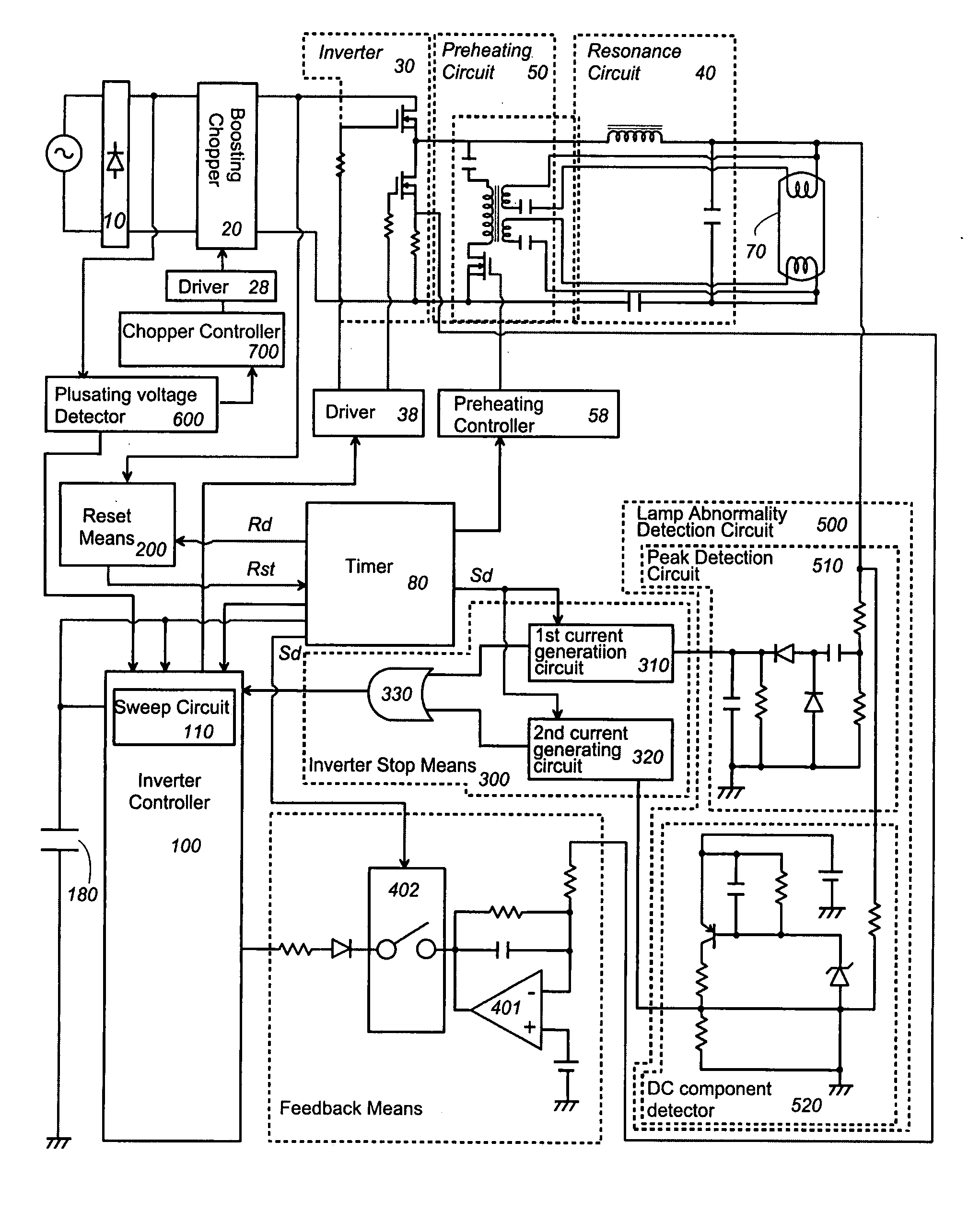
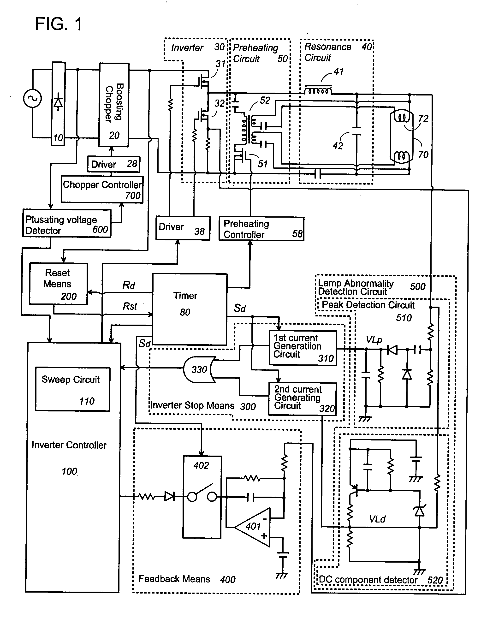
[0035] FIGS. 1 to 5 illustrate a discharge lamp ballast device in accordance with a first embodiment of the present invention. The discharge lamp ballast device is incorporated in an appliance mounting a discharge lamp, and includes a rectifier 10 rectifying an AC voltage from an AC power source, a chopper 20 receiving a pulsating DC voltage from the rectifier 10 to generate a boosted DC voltage, an inverter 30 converting the boosted DC voltage into a high frequency AC voltage, and a resonance circuit 40 resonating the high frequency AC voltage so that the resonating voltage from the resonant circuit is applied to the discharge lamp 70 for lighting the same. Further, the discharge lamp ballast device is equipped with a preheating circuit 50 which supplies a preheating current to filaments of the discharge lamp 70.

[0036] The chopper 20 includes a switching element which is turned on and off in accordance with a control signal from a chopper controller 700 to boost the pulsating DC v...

second embodiment

[0070]FIG. 12 illustrates a discharge lamp ballast device in accordance with a second embodiment of the present invention. The discharge lamp ballast device is basically identical in configurations and functions to the first embodiment, but includes a pulsating voltage detection circuit 600 which stops the inverter 30 and the chopper 20 when a pulsating DC voltage Vp from the rectifier 10 to the chopper goes below a predetermined value. The like parts are designated by like reference numerals, and no duplication explanation is made herein.

[0071] The rectifier 10 provides the pulsating DC voltage to the chopper 20 through a filtering capacitor 11. The chopper 20 includes a switching element 24 connected in series with an inductor 21 across the output ends of the rectifier 10, and a smoothing capacitor 26 connected in series with a diode 25 across the switching element 24. The switching element 24 is controlled by the chopper controller 700 to turn on and off, accumulating a smoothed...


PUM


Abstract

An inverter controller dives an inverter to operate at a switching frequency selectively from one of a preheating frequency (f1), a starting frequency (f2), and a lighting frequency (f3) which are different from each other, thereby giving a preheating mode, a starting mode, and a lighting mode. A reset means is provided to make the starting mode upon lowering of a voltage supplied to the inverter below a first threshold, while an inverter stop means is provided to stop the inverter upon detection of abnormality of a discharge lamp. A timer generates a signal determining the start of the preheating, starting, and / or lighting modes, and generates a reset signal disable signal for disabling the reset means, an inverter stop disable signal for disabling the inverter stop means. The inverter controller includes a frequency sweep means for varying the switching frequency gradually from the starting frequency to the lighting frequency. The timer disables the reset means only during a period starting from the selection of the preheating frequency and ending when the switching frequency varies to the lighting frequency, and disable the inverter stop means only during a period starting from the selection of the preheating frequency and ending when the switching frequency begins to vary from the starting frequency to the lighting frequency.

Description

TECHNICAL FIELD [0001] The present invention is directed to a discharge lamp ballast and a lighting appliance equipped with the discharge lamp ballast device. BACKGROUND ART [0002] As disclosed in Japanese Patent Publication No, 2003-203795, a discharge lamp ballast for a discharge lamp, especially for a fluorescent lamp of hot-cathode type is configured to provide a preheating mode for preheating filaments, a starting mode for applying a high voltage after the preheating mode to start the lamp, and thereafter a lighting mode for rated lighting or dimmed lighting of the lamp. The duration of the individual modes is given by use of a timer. The discharge lamp ballast device includes a chopper for boosting a DC power give by rectification of an AC power from an AC power source, an inverter for converting the DC power output from the chopper into an AC power, and a resonance circuit which resonates the high frequency AC power output from the inverter to apply the same to the discharge ...

Claims


Application Information

Patent Timeline
Patent Type & Authority Applications(United States)
IPC IPC(8): H05B41/36H05B37/04H05B41/04H05B41/06
CPCH05B41/295H05B41/2985H05B41/2981
Inventor HAMAMOTO, KATSUNOBUNISHIMOTO, KAZUHIROYAMANAKA, MASAHIROKANJA, TOSHIYA
Owner MATSUSHITA ELECTRIC WORKS LTD
Why Eureka
Try Eureka