Planar multiband antenna

a multi-band antenna and antenna technology, applied in the direction of simultaneous aerial operations, electrical equipment, structural forms of radiation elements, etc., can solve the problems of not being able to use a small cheap antenna, multiplexer to be employed, and difficulty in receiving from several different wireless transfer systems by a single broadband antenna, so as to achieve the effect of increasing the bandwidth of inventive antennas, particularly effective emission of free space, and increasing the bandwidth

Inactive Publication Date: 2007-12-27
FRAUNHOFER GESELLSCHAFT ZUR FOERDERUNG DER ANGEWANDTEN FORSCHUNG EV
View PDF14 Cites 32 Cited by
  • Summary
  • Abstract
  • Description
  • Claims
  • Application Information

AI Technical Summary

Benefits of technology

[0018] The central idea of embodiments of the present invention is that a planar multiband antenna of particularly advantageous features can be achieved by arranging the first radiation electrode between the ground area and a combination of the second radiation electrode and the third radiation electrode, wherein the third radiation electrode is arranged such that it completely encloses an external periphery of the second radiation electrode, wherein there is a gap between an external periphery of the second radiation electrode and an internal periphery of the third radiation electrode. A maximum dimension of the first radiation electrode thus is smaller than a maximum dimension of the third radiation electrode. The first radiation electrode which is at least partly between the second radiation electrode and the ground area here can serve as a radiator for an upper frequency range. In a lower frequency range, i.e. exemplarily in a frequency band having a lower frequency than the upper frequency range, the second radiation electrode and the third radiation electrode, which are further away from the ground area than the first radiation electrode, together can act as a radiating element. A gap between the second radiation electrode and the third radiation electrode which completely encloses the second radiation electrode allows the first radiation electrode, when operated in the upper frequency band, to be able to radiate electromagnetic waves into free space. Put differently, the gap between the external periphery of the second radiation electrode and the internal periphery of the third radiation electrode prevents the second and third radiation electrodes, which together are larger than the first radiation electrode, to shield off radiation from the first radiation electrode.
[0038] Such an implementation of an antenna allows particularly easy manufacturing, wherein the radiation characteristics of the antenna can be improved by the layers of low dielectric constant. A layer of very low dielectric constant reduces dielectric losses and also reduces surface waves occurring. In addition, the manufacturing is very favorable since only radiation electrodes which are supported by dielectric layers have to be processed. Thus, methods can be employed which allow patterning of planar layers on a support material, such as, for example, photolithographic methods. Methods of this kind are very cheap and offer very high precision. In addition, the dielectric layers supporting the radiation electrodes guarantee good mechanical stability for the antenna. A particularly easy and cheap manufacturing can be achieved by manufacturing the first, the second and the third dielectric layers from FR4 material (conventional circuit board material). The layer of low dielectric constant may be formed by air. It has been shown that an inventive antenna, with a corresponding design, can be manufactured extremely cheaply, wherein the radiation characteristics are not influenced negatively despite the cheap materials used.

Problems solved by technology

The disadvantage of using separate antennas, however, is that a multiplexer has to be employed.
Receiving from several different wireless transfer systems by a single broadband antenna is problematic since broadband antennas cannot usually be manufactured at low cost in a compact design.
If all the relevant systems are to be received by a single broadband antenna, this will not be possible using a small cheap antenna.
However, it is desirable in particular for mobile applications to use a circular polarization, since in this case the orientation of transmitting and receiving antennas is uncritical, whereas when using linear polarization, the orientation of the antennas has to be selected appropriately.
A series of antennas which may be integrated comprising a circular polarization are known, however many of the geometries which may be integrated comprise essential disadvantages for generating a circular polarization.
However, it is employed for broadband antennas of a resonant frequency or for antennas of several resonant frequencies close to one another, but not suitable for being employed in connection with multiband antennas.
The disadvantage of such an antenna assembly is that in this antenna two feeding channels have to be combined by a quadrature hybrid broadband extension line coupler in order to generate a circular polarization.
The disadvantage of the antennas described is that they comprise a complicated and not completely planar structure.

Method used


Image

  • Planar multiband antenna
  • Planar multiband antenna
  • Planar multiband antenna

Examples


Embodiment Construction

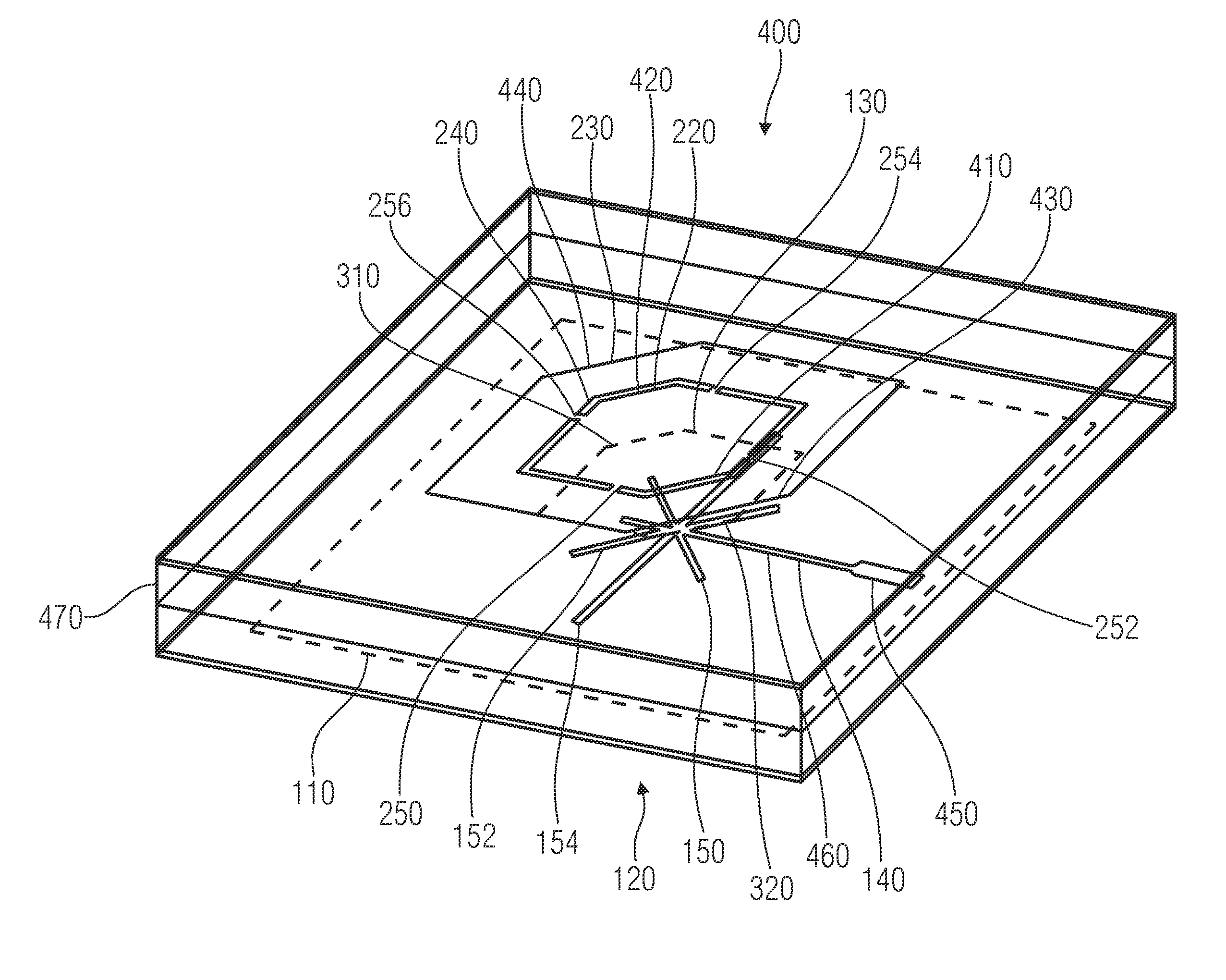
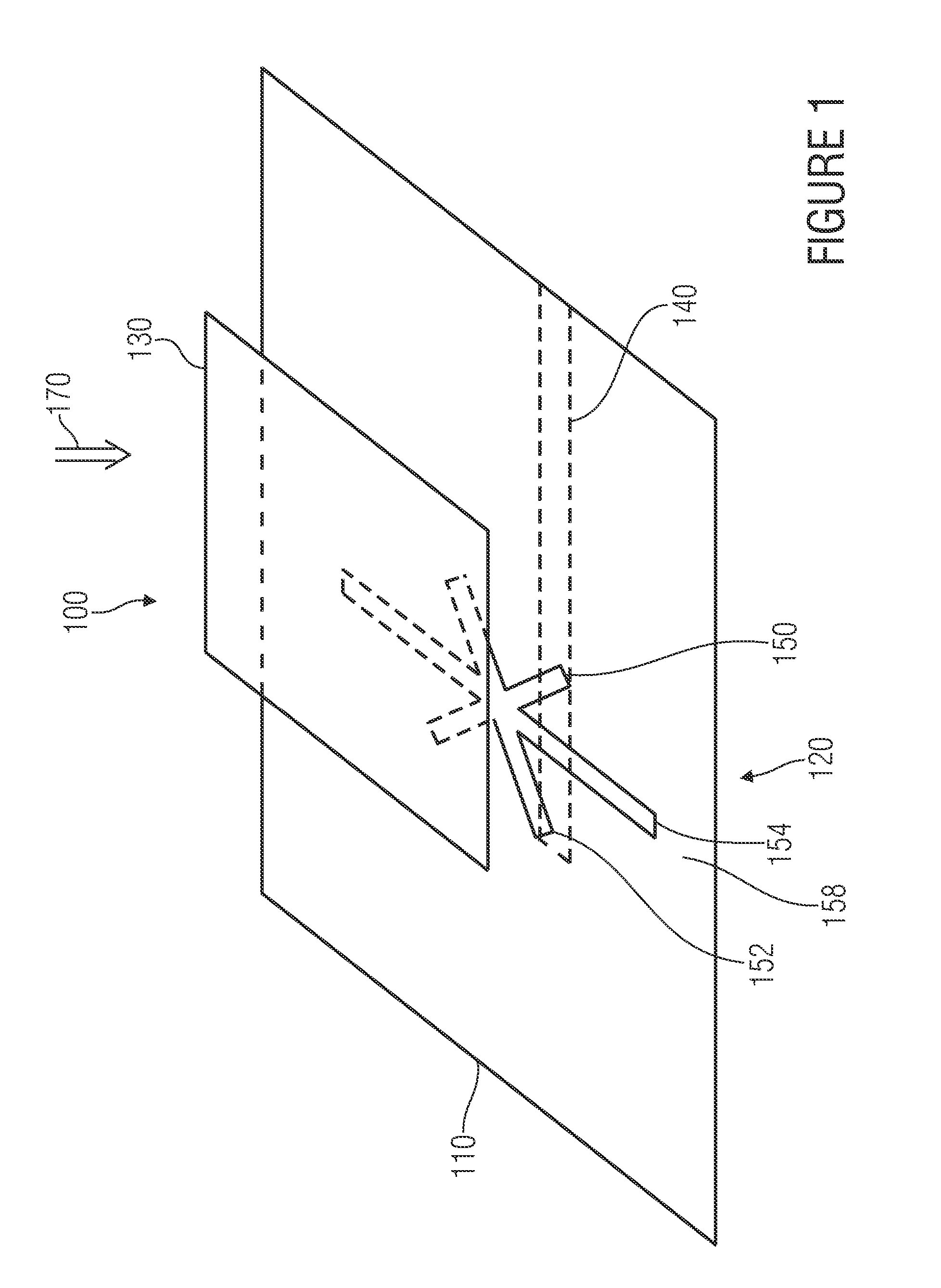
[0050]FIG. 1 shows a tilted image of a planar antenna structure from which an inventive antenna structure may be derived. The antenna structure in its entirety is referred to by 100. The antenna structure 100 includes a ground area 110 comprising an aperture 120. In addition, the antenna structure includes a radiation electrode 130 arranged above the ground area 110. A feeding line 140 which is shown here as a conducting strip is arranged below the ground area 110. The aperture 120 includes a first slot 150, a second slot 152 and a third slot 154. The first, second and third slots 150, 152, 154 each have a rectangular shape and represent an opening of the ground area 110. The first slot 150 and the second slot 152 are arranged so as to form a cross. The lengths of the first slot 150 and the second slot 152 in the embodiment shown are equal. The third slot 154 is longer than the first slot 150 and the second slot 152 and intersects the first and second slots 150, 152 in the region in...


PUM


Abstract

The present invention provides a planar multiband antenna having a ground area, a first radiation electrode, a second radiation electrode, a third radiation electrode and a feeder. The feeder is implemented to feed the first radiation electrode. The first radiation electrode is arranged at least partly between the ground area and the second radiation electrode and does not protrude from an external periphery of the third radiation electrode. The third radiation electrode is arranged such that it completely surrounds an external periphery of the second radiation electrode, wherein there is a gap between the second radiation electrode and the third radiation electrode.

Description

CROSS-REFERENCE TO RELATED APPLICATIONS [0001] This application is a continuation of copending International Application No. PCT / EP2006 / 001661, filed Feb. 23, 2006, which designated the United States and was not published in English.BACKGROUND OF THE INVENTION [0002] 1. Field of the Invention [0003] The present invention generally relates to a planar multiband antenna, in particular to an aperture-coupled circularly polarized planar dual-band antenna which can be employed in ISM bands from 2.40 GHz to 2.48 GHz and 5.15 GHz to 5.35 GHz. [0004] 2. Description of the Related Art [0005] Wireless systems which have to function in several frequency bands are being developed more frequently. Frequently, compact antennas are necessary to keep the setup volume of the antennas small and to allow usage in portable devices. [0006] It is possible to provide a separate antenna for each frequency band to be used. The disadvantage of using separate antennas, however, is that a multiplexer has to be...

Claims


Application Information

Patent Timeline
Patent Type & Authority Applications(United States)
IPC IPC(8): H01Q1/38H01Q5/364H01Q5/392
CPCH01Q9/0414H01Q9/0428H01Q5/392H01Q5/364H01Q9/0471
Inventor POPUGAEV, ALEXANDERWANSCH, RAINER
Owner FRAUNHOFER GESELLSCHAFT ZUR FOERDERUNG DER ANGEWANDTEN FORSCHUNG EV
Why Eureka
Try Eureka