Mode-locked laser device

a laser device and mode-locked technology, applied in the direction of laser details, optical resonator shape and construction, electrical equipment, etc., can solve the problems of large reabsorption loss, large device size and cost, poor stability, etc., and achieve high output stability and simple structure

Inactive Publication Date: 2007-12-27
FUJIFILM CORP
View PDF20 Cites 22 Cited by
  • Summary
  • Abstract
  • Description
  • Claims
  • Application Information

AI Technical Summary

Benefits of technology

[0011]In view of the above-described circumstances, the present invention is directed to provide a mode-locked laser device that is compact, has a simple structure and high output stability.
[0017]In the mode-locked laser device of the invention, output light may have a lasing wavelength corresponding to a wavelength of a peak in fluorescence spectrum of the solid-state laser medium, at which four-level system lasing is performed. It should be noted that the “four-level lasing” includes “quasi-four-level system” that behaves similarly. For example, a wavelength at which four-level lasing is performed, such as lasing at a wavelength of 1050 nm by the Yb:YAG, is included. In the four-level system lasing, rate of decrease in lasing efficiency, which decreases as the beam diameter of the excitation light within the laser medium increases, is smaller than that of the three-level system, and therefore high lasing efficiency can be achieved without reducing the beam diameter of excitation light within the laser medium as small as that required in the three-level system. Therefore, the four-level system lasing is more suitable for the mode-locked laser device of the invention.

Problems solved by technology

This increases the number of parts forming the device, thereby making the device large and expensive, and poor in stability.
The reason for increasing the overlap between the excitation light and the lasing light within the solid-state laser medium is that, if the beam diameter of the excitation light is smaller than the beam diameter of the lasing light within the solid-state laser medium, a large reabsorption loss occurs at areas where no excitation light is present and the lasing efficiency decreases.
In contrast, if the beam diameter of the excitation light is larger than the beam diameter of the lasing light within the solid-state laser medium, even areas where no lasing light is present, i.e., areas which do not contribute to lasing are excited and the lasing efficiency also decreases, and therefore sufficient high-density excitation may not be achieved.
This increases the distance from the condensing lens to the solid-state laser medium, and necessitates a complicated excitation optical system to efficiently condense the light to have a small diameter.
Therefore, such device also has a complicated resonator structure and a complicated excitation optical system.
As described above, conventional mode-locked laser devices have multiple concave mirrors and thus have a complicated structure.
They have poor output stability, and are large and expensive due to the large number of parts.
In addition, they use a complicated excitation optical system to improve excitation efficiency, and this further increases the size of such devices.

Method used


Image

  • Mode-locked laser device
  • Mode-locked laser device
  • Mode-locked laser device

Examples


Embodiment Construction

[0028]Hereinafter, embodiments of the present invention will be described in detail.

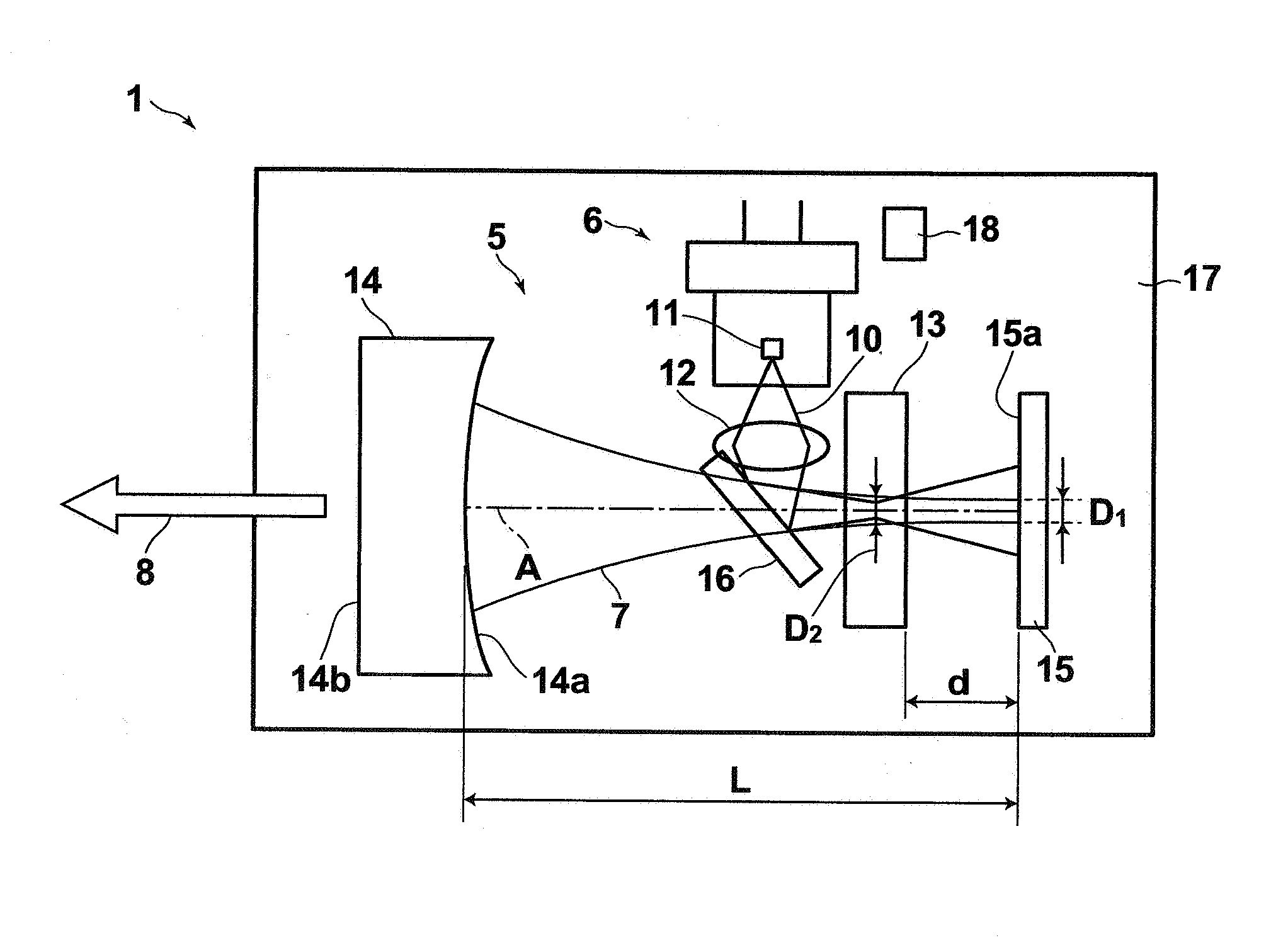
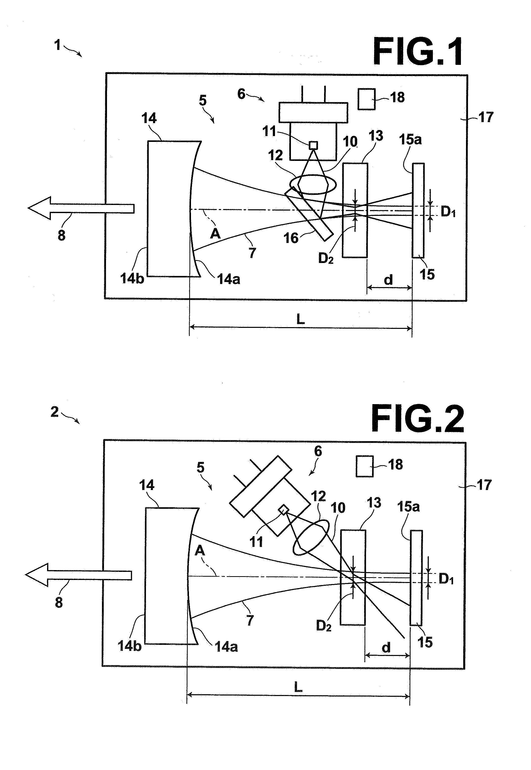
[0029]FIG. 1 is a plan view showing the schematic structure of a mode-locked laser device 1 according to a first embodiment of the present invention. The mode-locked laser device 1 includes a Fabry-Perot resonator 5, a solid-state laser medium 13 disposed in the resonator 5, a mode-locking element 15, and an exciting means 6 for applying excitation light 10 to the solid-state laser medium 13. The mode-locking element 15 is a saturable absorber mirror, which forms one of the ends of the resonator 5. The other end of the resonator 5 is formed by an output concave mirror 14. The resonator 5 includes no other mirror for reflecting the lasing light than the saturable absorber mirror 15 and the output mirror 14 forming the ends of the resonator, and the resonator 5 is structured as a linear resonator.

[0030]The exciting means 6 is formed by a semiconductor laser 11 for outputting a laser beam which serves a...


PUM


Abstract

A mode-locked laser device includes a Fabry-Perot resonator, a mode-locking element disposed within the resonator, a solid-state laser medium disposed within the resonator, and exciting means for applying excitation light to the solid-state laser medium. The opposite ends of the resonator, the mode-locking element and the solid-state laser medium are disposed to provide an average beam diameter of lasing light of not more than 150 μm on the mode-locking element and an average beam diameter of the lasing light of not more than 200 μm within the solid-state laser medium.

Description

BACKGROUND OF THE INVENTION[0001]1. Field of the Invention[0002]The present invention relates to a mode-locked laser device, and particularly to a mode-locked laser device provided with a solid-state laser medium and a mode-locking element within a Fabry-Perot resonator.[0003]2. Description of the Related Art[0004]As a conventional technique for continuously generating optical short pulse train, a mode locking method is used in which a solid-state laser medium placed in a resonator is excited, for example, with a semiconductor laser, and phases of many lasing longitudinal modes are locked. The mode locking method includes, for example, an active method where an optical modulator is disposed in the resonator to apply loss modulation, and a passive method where a saturable absorber whose absorption coefficient changes nonlinearly is disposed in the resonator to achieve passive mode locking. A passive mode-locked laser device using a saturable absorber has been proposed, for example, i...

Claims


Application Information

Patent Timeline
Patent Type & Authority Applications(United States)
IPC IPC(8): H01S3/098H01S3/091H01S3/08H01S3/092
CPCH01S3/042H01S3/08H01S3/09415H01S3/1685H01S3/1618H01S3/163H01S3/1673H01S3/1118
Inventor ADACHI, TAKASHIYAMAZOE, SHOGO
Owner FUJIFILM CORP
Why Eureka
Try Eureka