
Double Row Self-Aligning Roller Bearing And Main Shaft Support Structure Of Wind Power Generator

a self-aligning, roller bearing technology, applied in the direction of sliding contact bearings, electric generator control, machines/engines, etc., can solve the problems of high risk, high reliability of bearings that support the main shaft of wind power generators, and large amount of labor, so as to achieve low torque, prevent edge stress, and control the position of contact points

Active Publication Date: 2007-12-27
NTN CORP
View PDF15 Cites 20 Cited by
  • Summary
  • Abstract
  • Description
  • Claims
  • Application Information

AI Technical Summary

Benefits of technology

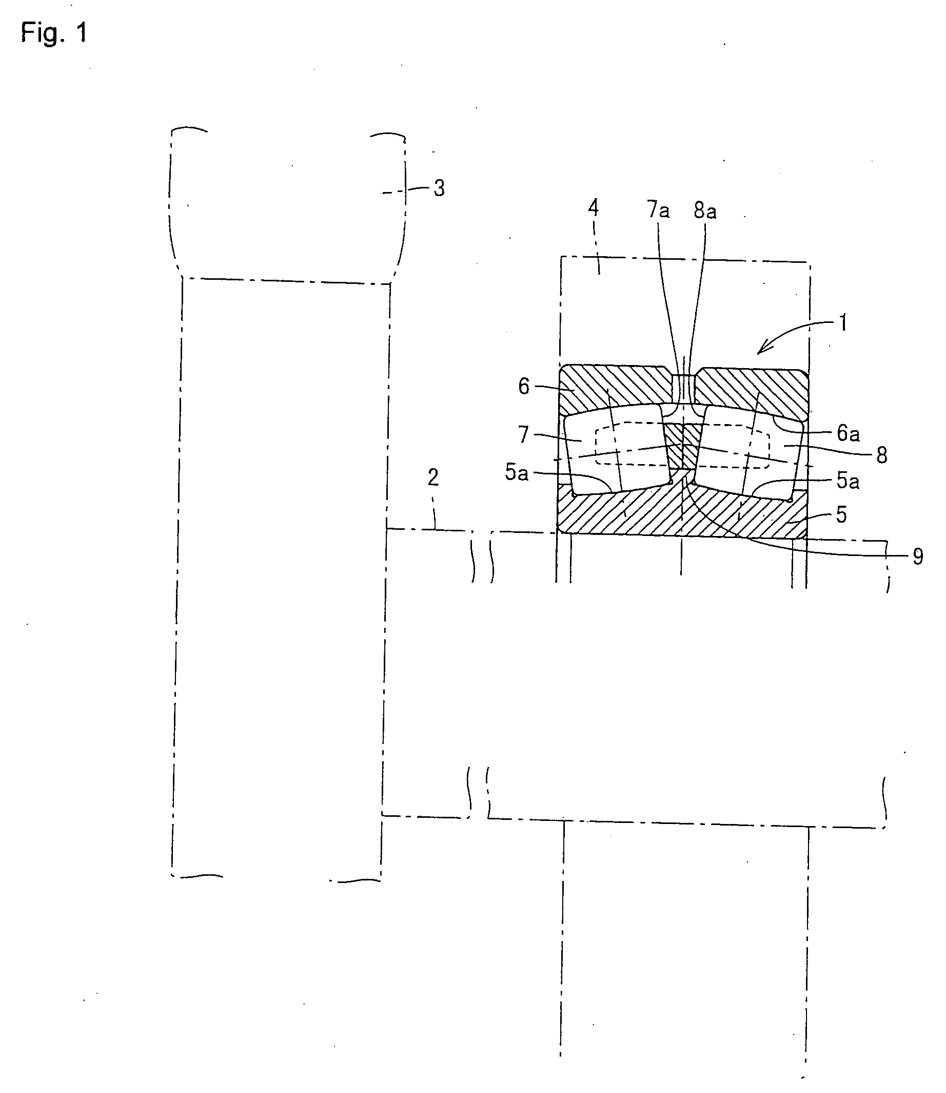
[0011] It is an object of the present invention to provide an economical double row self-aligning roller bearing that can implement appropriate support according to a load at each row and extend a substantial life and does not waste its material, and a main shaft support structure of a wind power generator using the above bearing.
[0012] It is another object of the present invention to provide a double row self-aligning roller bearing that can extend the life of a highly-loaded spherical roller especially.

Problems solved by technology

Since a power generator body comprising a windmill is set at a height of several tens of meters in a case of a large wind power generation facility, a large amount of labor is needed and high risks are accompanied in maintaining the bearing that supports the main shaft of the blade of the windmill.
Therefore, the bearing that supports the main shaft of the wind power generator requires high reliability and a long durable life.
Furthermore, since the contact position is at the upper part of the side surface of the center rib, a contact ellipse is cut and an edge stress is generated at the upper end and as a result, this part could be worn at an early stage or peeled and the like.
Although it is considered to increase the size of the bearing in order to correspond to the high load, it is a waste for the spherical roller on the low-loaded side.

Method used


Image

  • Double Row Self-Aligning Roller Bearing And Main Shaft Support Structure Of Wind Power Generator
  • Double Row Self-Aligning Roller Bearing And Main Shaft Support Structure Of Wind Power Generator
  • Double Row Self-Aligning Roller Bearing And Main Shaft Support Structure Of Wind Power Generator

Examples


Embodiment Construction

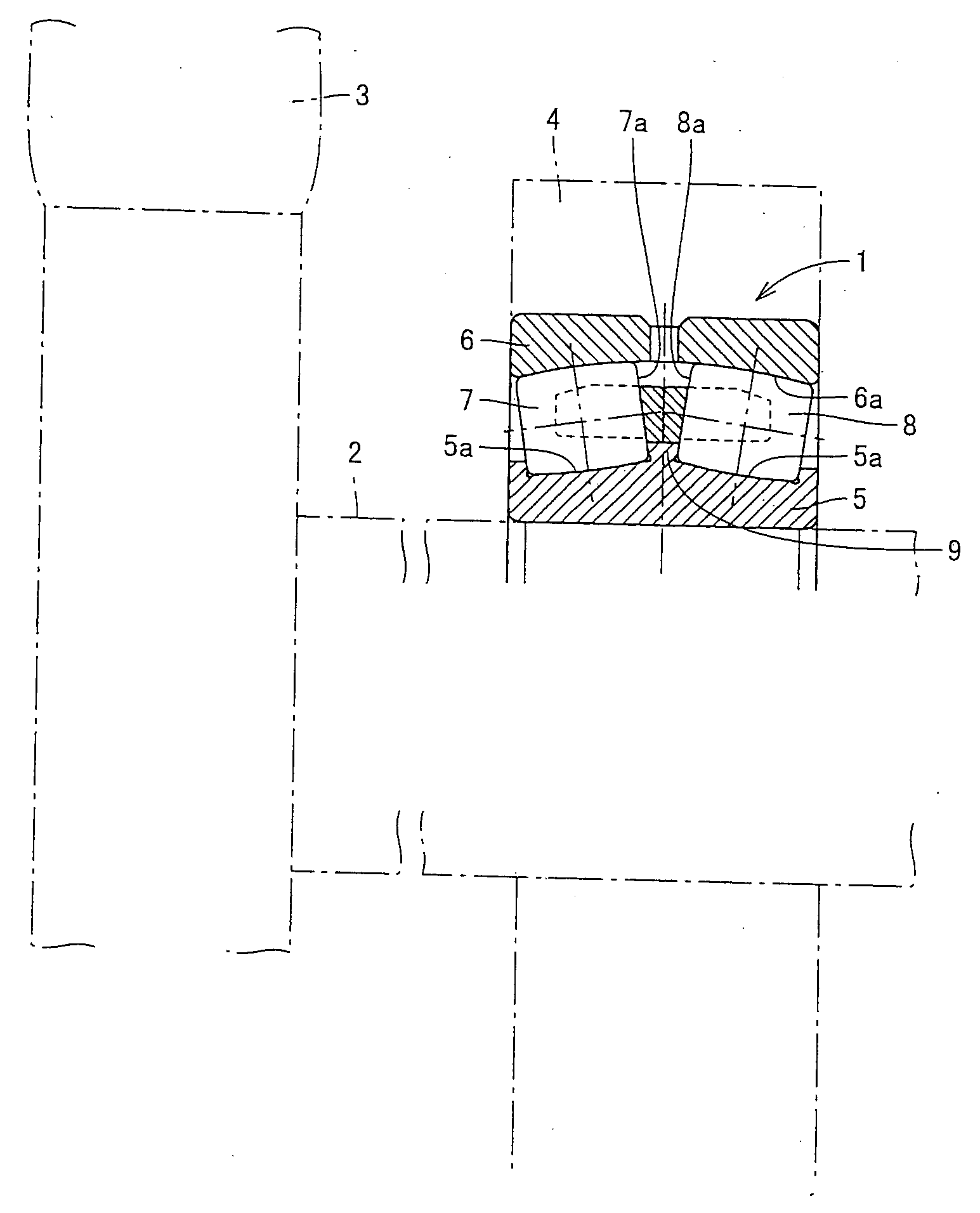
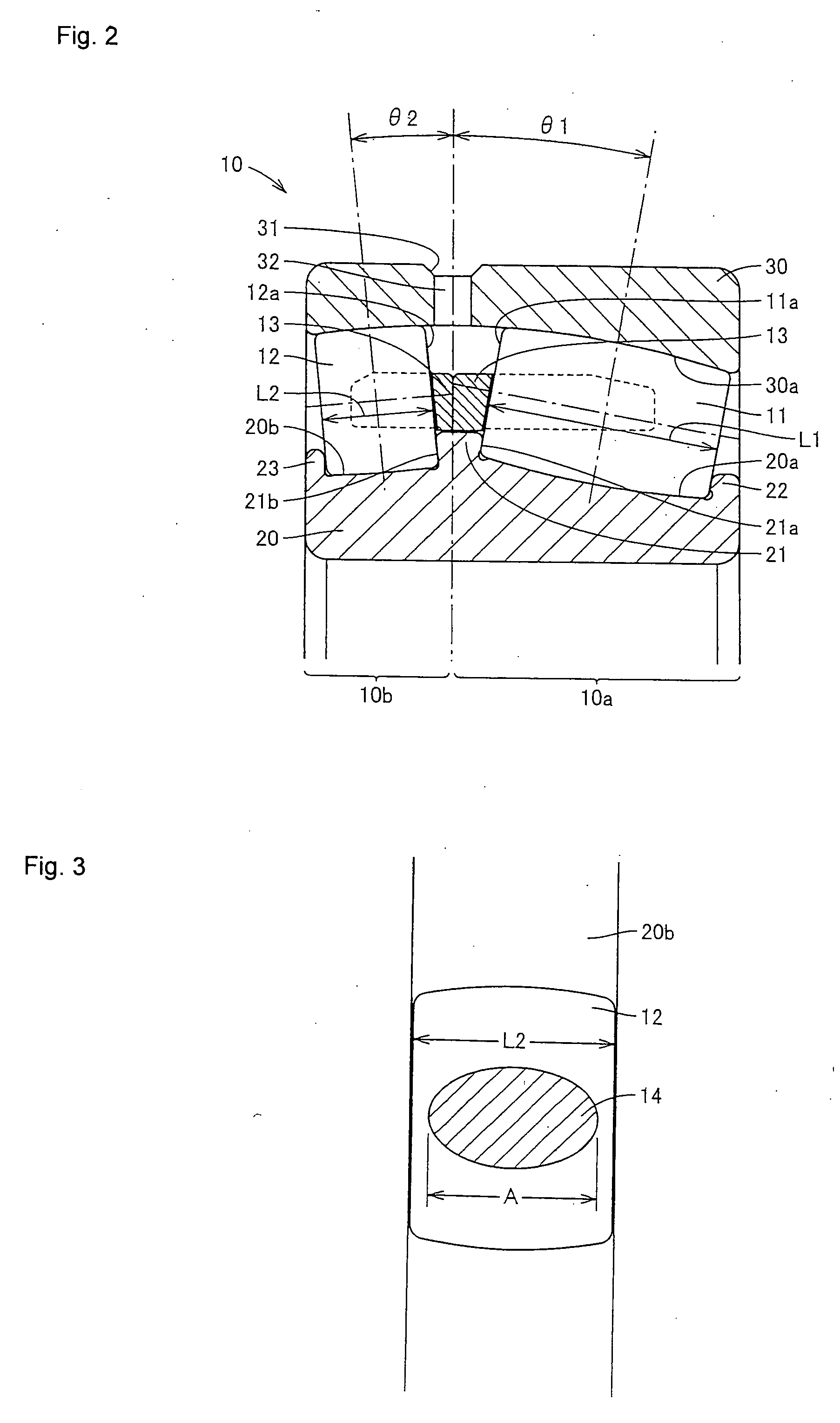
[0050] A double row self-aligning roller bearing according to one embodiment of the present invention will be described with reference to FIGS. 2 and 3.

[0051] A double row self-aligning roller bearing 10 comprises an inner ring 20, an outer ring 30, spherical rollers 11 and 12 arranged in double rows between both track rings, and a retainer 13 retaining the spherical rollers 11 and 12. The retainer 13 is provided separately for each row. A track surface 30a of the outer ring 30 is formed into a spherical shape and the outer peripheral surface of each of the spherical rollers 11 and 12 has a spherical configuration so as to follow the track surface 30a of the outer ring 30.

[0052] The outer ring 30 has an oil groove 31 at the middle position in its outer diameter surface and further has an oil hole 32 penetrating from the oil groove 31 to its inner diameter surface. The oil hole 32 is provided at one or more positions in the circumferential direction.

[0053] The inner ring 20 accord...


PUM


Abstract

When it is assumed that the length of the spherical roller (11) in one row is L1, the length of the spherical roller (12) in the other row is L2, and the length of the longer axis of a contact ellipse (14) generated on the contact surface between the spherical roller (12) in the other row and a track ring (20b) is A, the relation such thatL2<L1 andL2>Ais satisfied.

Description

TECHNICAL FIELD [0001] The present invention relates to a double row self-aligning roller bearing and more particularly, to a double row self-aligning roller bearing in which unequal loads are applied to spherical rollers in right and left rows and a main shaft support structure of a wind power generator comprising the above bearing. BACKGROUND ART [0002] Recently, wind power generation that uses clean and inexhaustible energy has attracted attention. Since a power generator body comprising a windmill is set at a height of several tens of meters in a case of a large wind power generation facility, a large amount of labor is needed and high risks are accompanied in maintaining the bearing that supports the main shaft of the blade of the windmill. Therefore, the bearing that supports the main shaft of the wind power generator requires high reliability and a long durable life. [0003] A self-aligning roller bearing suitable for rotatably supporting the main shaft of the wind power gener...

Claims


Application Information

Patent Timeline
IPC IPC(8): F16C23/08F03D11/00F16C33/36H02K7/08F16C33/58F16C19/28
CPCF03D11/0008F05B2250/24F05B2250/241F16C23/086F16C33/36F16C2300/14F16C2240/34H02K7/183Y02E10/722Y02E10/725H02K7/1838F16C19/50H02K7/083F03D80/70F16C2360/31F16C19/38F16C2240/40F16C2240/76Y02E10/72
Inventor MORI, NOBUYUKI
Owner NTN CORP
Learn More