System and method of generating electrical stimulation waveforms as a therapeutic modality

a technology of electrical stimulation and waveforms, applied in the field of system and method of generating electrical stimulation waveforms, can solve the problems of not being able to store complex series of waveform treatments, not being able to update software, and being limited by the impedance of the skin. , to achieve the effect of convenient upgrading and process facilitation

Inactive Publication Date: 2007-12-27
AXIOM WORLDWIDE
View PDF12 Cites 105 Cited by
  • Summary
  • Abstract
  • Description
  • Claims
  • Application Information

AI Technical Summary

Benefits of technology

[0014] As the DDS is capable of a wide variety of automatic waveform manipulation controlled by a few simple commands from a processor, the system is easily upgraded via software. A software upgrade could include a new set of commands that the processor would issue to change the frequency limits of an earlier DDS system, for example from 4000 to 10000 Hz, to 4000 to 100 kHz instantly. Further, software upgrades could allow for expansion as new waveforms are approved for medical use.
[0015] While some DDS technology can also

Problems solved by technology

These systems are limited by the impedance of the skin.
But purely analog systems require calibration, are not software updatable, can not store complex series of waveform treatments, and can not “remember” individual patient settings.
But the PWM system is extremely processor intensive, particularly if the system provides more than one channel of therapy.
Further, because of the nature of the analog filter, every time the pulse is changed from a “1” to a “0”, or vice versa, the filter outputs a spectrum of unwanted noise which requires filtering.
The limitations of the conversion process in terms of waveform stepping and the additional noise created requires the system to aggressively filter the signal to achieve as smooth a sine wave as possible for deliver

Method used


Image

  • System and method of generating electrical stimulation waveforms as a therapeutic modality
  • System and method of generating electrical stimulation waveforms as a therapeutic modality
  • System and method of generating electrical stimulation waveforms as a therapeutic modality

Examples


Embodiment Construction

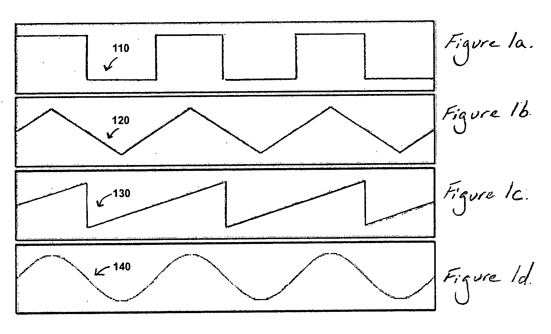
[0036]FIGS. 1a-d illustrate various examples of waveforms utilized by electrical stimulation to excite cellular function, namely a pulsed DC or square wave 110, a triangular wave 120, a sawtooth wave 130, and a sine wave 140, respectively. Each of the waveforms illustrated in FIGS. 1a-d is monophasic, wherein current is passed from one electrode on a patient's body to another electrode on the patient's body in only one direction. However, each of the waveforms illustrated in FIGS. 1a-b may be amplified to a biphasic state.

[0037] As shown by FIG. 1a, with a pulsed DC or square wave 110, the current that is passed from a one electrode to another may have a rapid ascent to a maximum level, where the current level may be held before being abruptly dropped down to a minimum level. With triangular waves 120, as shown in FIG. 1b, the current level passed from one electrode to another may be ramped up until reaching a maximum level, whereupon the current level may be ramped back down. A tr...


PUM


Abstract

Embodiments of the present invention provide an apparatus and method of generating electrical stimulation waveforms using Direct Digital Synthesis (DDS). The waveform generation substantially reduces intensive processor calculations and commands required for the generation of waveforms via Pulse Width Modulation (PWM). DDS technology is integrated into single-integrated circuit components, capable of generating waveforms based on singular digital word commands. The use of DDS integrated circuits allows for rapid changes in frequencies, automatically sweeps frequencies between user defined limits, and are capable of a wide range of frequencies. Further, utilization of DDS in waveform generation allows for software updatable functionality. Additionally, because DDS technology outputs a smooth sine wave, the need for extensive filtering is drastically reduced. Further, DDS technology can be utilized in an amplitude modulation stage beyond the DDS waveform generator, further reducing the burden on processor systems.

Description

RELATED APPLICATION [0001] This application claims the benefit of U.S. Provisional Application No. 60 / 812,486, filed Jun. 9, 2006, which is incorporated herein by reference in its entirety.BACKGROUND OF THE INVENTION [0002] Embodiments of the present invention generally relate to a system and method of generating electrical stimulation waveforms, and more particularly to a method of generating electrical stimulation waveforms using Direct Digital Synthesis (DDS). [0003] Electrical stimulation has been utilized and refined for decades as a means to activate and strengthen muscle, improve circulation, reduce edema and inflammation, reduce pain, and to fatigue muscle so as to reduce muscle spasm and tremors. The type of waveform utilized has been evolved for decades in medical practice, as has the technology used to produce it. Constant current (DC or galvanic current), pulsed Monophasic (uni-directional), Biphasic (bi-directional) waveforms (including square, triangle, trapezoidal, an...

Claims


Application Information

Patent Timeline
IPC IPC(8): G06F1/02
CPCA61N1/36014A61N1/323H03G3/3021G06F1/0321A61N1/36034
Inventor JOHNSON, SCOT L.DEWEERD, ANDREW
Owner AXIOM WORLDWIDE
Why Eureka
Try Eureka