Main element for an electrical machine

a main element and electrical machine technology, applied in the direction of dynamo-electric machines, magnetic circuit shape/form/construction, structural associations, etc., can solve the problems of limited coil geometry and relatively expensive assembly types, and achieve the effect of easy connection and tighter coil winding

Inactive Publication Date: 2008-01-03
ROBERT BOSCH GMBH
View PDF9 Cites 5 Cited by
  • Summary
  • Abstract
  • Description
  • Claims
  • Application Information

AI Technical Summary

Benefits of technology

[0014]The poles are preferably designed as one-piece components, however, e.g., out of iron, sintered metal, or another soft-magnetic material. This has the advantage that they can be easily connected with the flux return ring. The poles, however, can be composed of a bundle of lamina that are positioned next to each other axially, end to end. To attach the poles to the flux return ring, the lamina of a pole are connected with each other in a suitable manner in the region of the pole shoe, particularly in the region of the surface of the pole shoe facing the flux return ring.
[0015]The coils can be attached to the pole shoes, e.g., by winding the coils directly onto the pole shoes. To this end, the poles are transported to the winding machine. Since the poles are not installed on the flux return ring when the coils are put in place, the windings of the coils can be wound more tightly around the pole shoes. As an alternative, the coils can be prefabricated as separate components and subsequently installed on the pole shoes by sliding them onto the pole shoes from their free end. The winding of the coils can also be tighter in this embodiment, since the coils can be slid onto the pole shoes directly. They do not have to be guided around the pole horns, as is required for the stator according to WO 92 / 10020 A.

Problems solved by technology

This type of assembly is relatively expensive, because a separate step is required to connect the two lamina bundle parts of the stator with each other.
Also, when the coils are installed in this manner, the geometry of the coils is limited, since the coils must be wide enough that they can be guided around the pole horns when they are placed on the pole shoe.

Method used


Image

  • Main element for an electrical machine
  • Main element for an electrical machine

Examples


Embodiment Construction

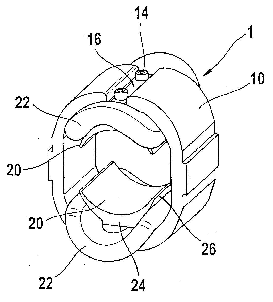
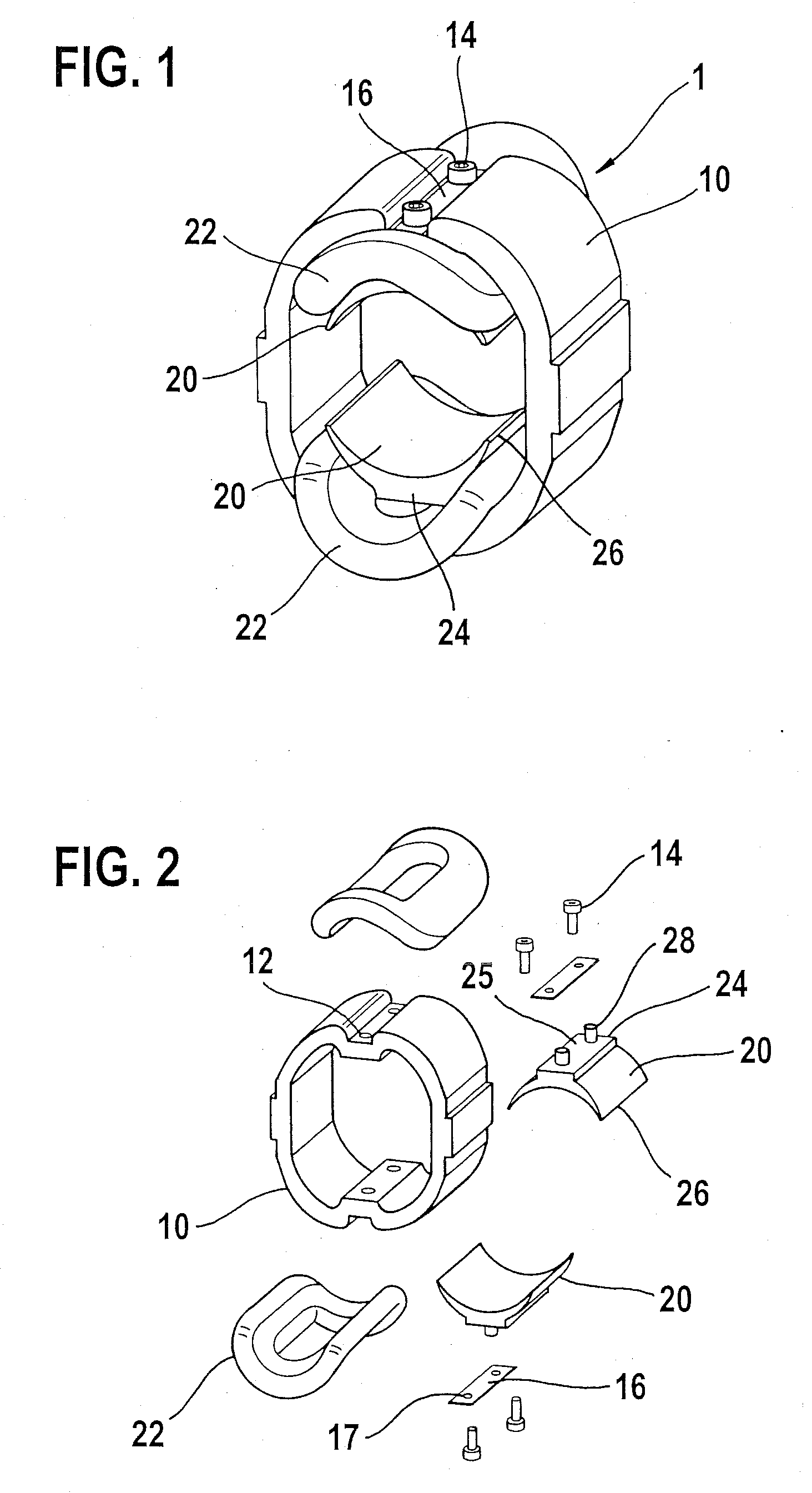
[0022]The embodiment of the inventive main element depicted schematically in FIG. 1 is a stator 1 of a two-pole universal motor with an inner-rotor design. Flux return ring 10 of stator 1 is composed—in a manner known per se—of a bundle of lamina that are positioned next to each other axially, end to end (not shown). Stator 10 includes two diametrically opposed poles 20. Poles 20 are positioned over pole shoes 24 on flux return ring 10 and point radially inwardly. Poles 20 with pole shoes 24, which transition into pole horns 26 in the circumferential direction, are designed as one-piece components. A coil 22 is mounted on each one, for field excitation.

[0023]According to the present invention, poles 20 are connectable with flux return ring 10. In the embodiment shown, poles 20 are detachably connected with flux return ring 10 using a screw connection. To this end, in the exemplary embodiment shown, two boreholes 12 for each pole 20 are provided in flux return ring 10. Accordingly, p...


PUM


Abstract

A main element, in particular a stator, for an electrical machine, in particular for a universal motor, includes a flux return ring with at least two poles that are situated radially on the flux return ring, and each of which accommodates at least one coil, the poles can be connected with the flux return ring.

Description

CROSS-REFERENCE TO A RELATED APPLICATION[0001]The invention described and claimed hereinbelow is also described in German Patent Application DE 102006029628.1 filed on Jun. 28, 2006. This German Patent Application, whose subject matter is incorporated here by reference, provides the basis for a claim of priority of invention under 35 U.S.C. 119(a)-(d).BACKGROUND OF THE INVENTION[0002]The present invention relates to a main element, particularly a stator, for an electrical machine, in particular for a universal motor.[0003]Publication WO 92 / 10020 A makes known a stator for a two-pole electrical machine that is composed of a two-part lamina bundle to accommodate the stator winding. The stator is divided in the longitudinal direction, thereby forming two symmetrical lamina bundle parts, the parting plane of which extends through the middle of the two diametrically opposed legs of the magnetic flux return. To simplify manufacture and assembly, the two lamina bundle parts are held togeth...

Claims


Application Information

Patent Timeline
Patent Type & Authority Applications(United States)
IPC IPC(8): H02K1/18
CPCH02K1/146
Inventor HABELE, MICHAEL
Owner ROBERT BOSCH GMBH
Why Eureka
Try Eureka