Motion Activated Power Source

a technology of motion and power source, which is applied in the direction of electrical apparatus, dynamo-electric machines, mechanical energy handling, etc., can solve the problems of limited harvesting of energy by prior art devices, and achieve the effect of reducing the width of the magnetic cavity, maximizing the harvesting potential of invention, and maximizing the strength of the magnetic field within the cavity

Inactive Publication Date: 2008-01-03
KINERGI
View PDF9 Cites 18 Cited by
  • Summary
  • Abstract
  • Description
  • Claims
  • Application Information

AI Technical Summary

Benefits of technology

[0021] (1) To increase the coil momentum and sensitivity to lower energy vibrations, and to overcome the inductive resistance threshold of the permanent magnets.
[0025] The magnetic field is provided by a permanent magnet or an array of permanent magnets. Preferably the magnetic flux is non linear and the permanent magnets are configured to maximize the magnetic flux over the path of the moving coil to maximize current generation.
[0028] As the coils pass through the field created by permanent magnets arranged around the coils they generate an AC voltage, which appears at the coil output wires. The voltage generated can be used to charge a capacitor or a battery. The invention may be used as a movement energy sensor. By attaching the invention to a moving object it can give an indication of movement intensity. This is because the AC voltage generated by the invention is proportional to how vigorously the object moves. To maximize the harvesting potential of the invention, the magnetic field strength within the cavities is maximized. This is achieved by reducing the width of the magnetic cavity and the placement of smaller magnets in specific alignments within the cavity, increasing the flux density through which the coil must pass. The smaller magnets act as ‘boosters’ to the diminishing field passing through the coil.
[0029] A second embodiment has the one coil separated into 3 or 4 coils connected in series. This is specific to the magnetic circuit design and maximizes the harvesting efficiency of the invention.
[0031] The field versus distance from a pole face of a magnet is proportional to the inverse square of the distance. This invention is in part based the consequences of applying this principle to a coil passing through a field generated by two permanent magnets. The thicker the coil the further the magnets must be placed apart, and consequently the weaker (proportional to the inverse square of the separation) field in between. This invention is in part predicated the realisation that magnetic separation is a crucial point of the design of magnetic circuits. The design of this embodiment maximizes the slot width, slot number, placement and pattern in a magnet, whilst at the same time maximizing the magnetic field strength within the slots. The coil is split into several coils connected in series, specifically to fit into the number of slots in the magnet. As all of the coils are resiliently fixed to move as one, physically connected by the torsion bar, they will respond to external excitement in unison, acting as one coil with the same number of turns. Increasing the flux density in the oscillation path of the coils, increases the combined three-coil output voltage for a given inertial input. This procedure maximizes the harvesting potential of the invention.
[0039] The device is tuned by assessing the major frequencies of vibration available in the application, and the displacement distance of that vibration. The mechanical resonance (i.e. the coil mass-spring resonance) of the device is designed to resonate at the frequency. The displacement distance is related to the energy in each oscillation and is used to evaluate the spring constant (or ‘spring-ey-ness’) of the springs. The thicker the cross section of the springs the more spring resistance the spring has and the more powerful the recoil.

Problems solved by technology

These prior art devices are limited to harvesting energy from dynamic motion or vibration energy inputs which require a higher threshold typically frequencies above 10,000 hz than is available from many environmental motion and vibration sources.

Method used


Image

  • Motion Activated Power Source
  • Motion Activated Power Source
  • Motion Activated Power Source

Examples


second embodiment

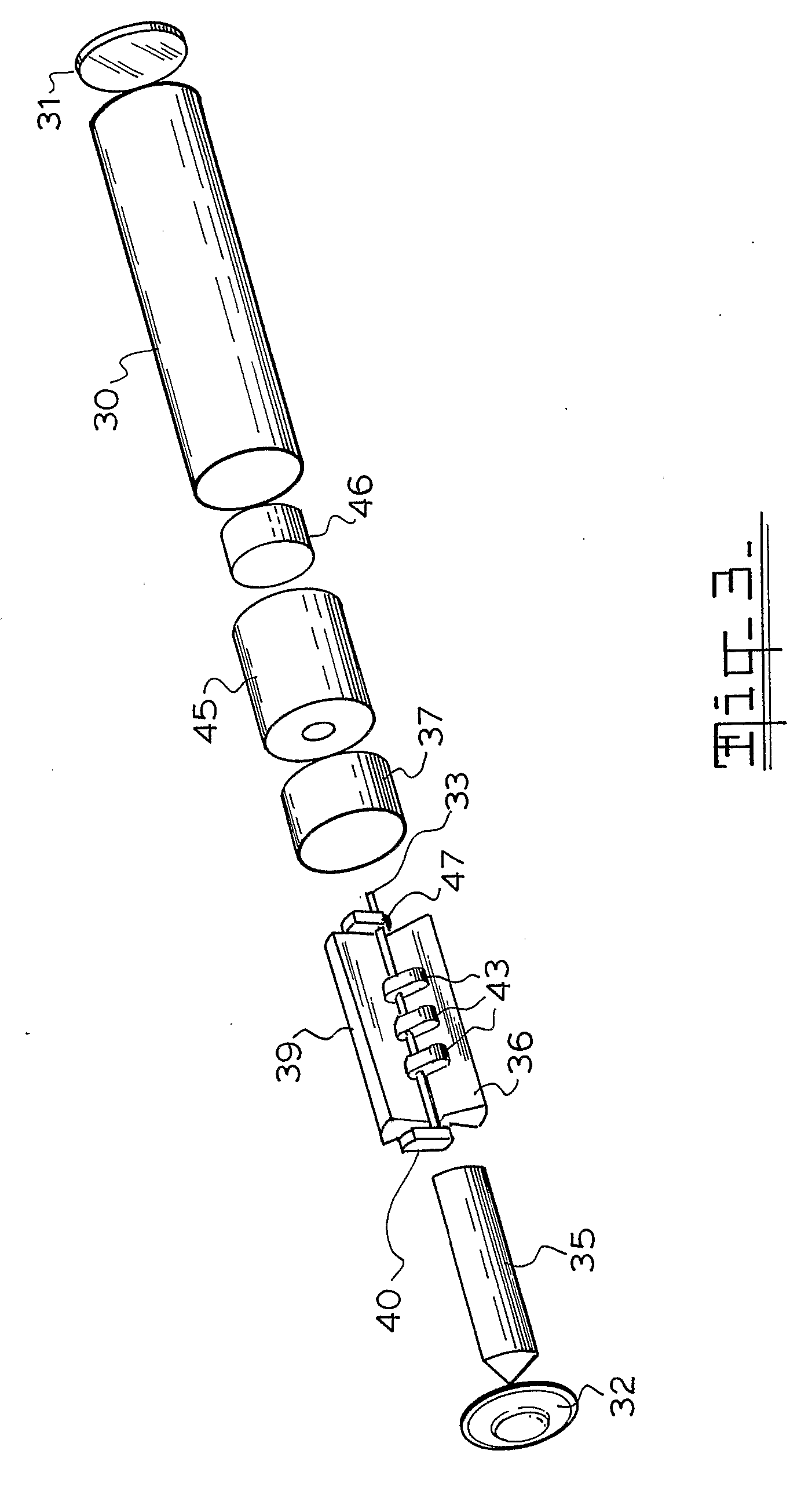
[0046]FIG. 3 is the exploded drawing of the device.

[0047]FIG. 4 is a schematic drawing of the electronic circuit used in the device;

third embodiment

[0048]FIG. 5 is an exploded view of the invention;

[0049]FIG. 6 is a cross section of the embodiment shown in FIG. 5;

[0050]FIG. 7 illustrates the magnetic polarity set up of the embodiment of FIG. 5;

[0051]FIG. 8 illustrates the coil series connection sequence of the embodiment of FIG. 5.

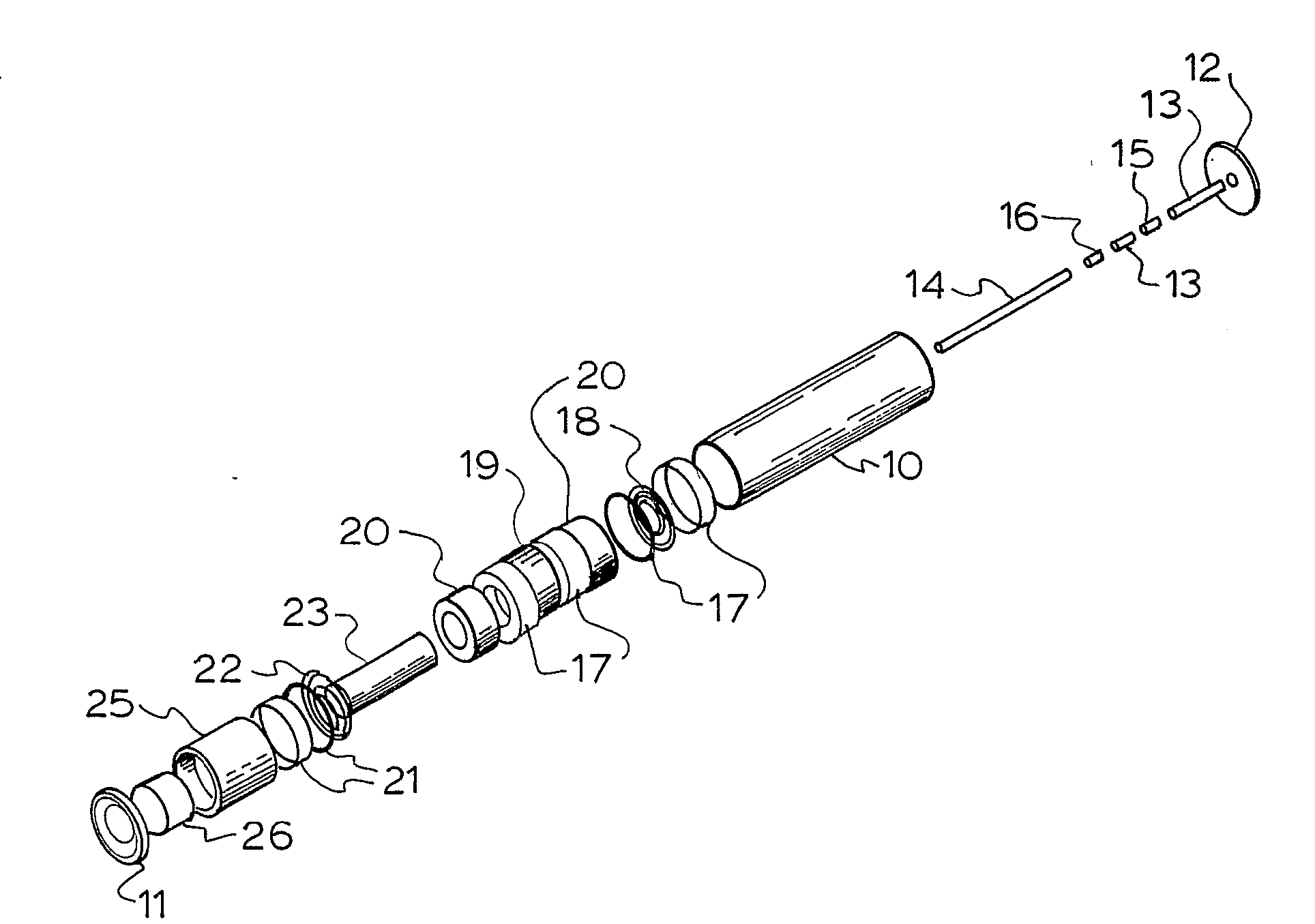
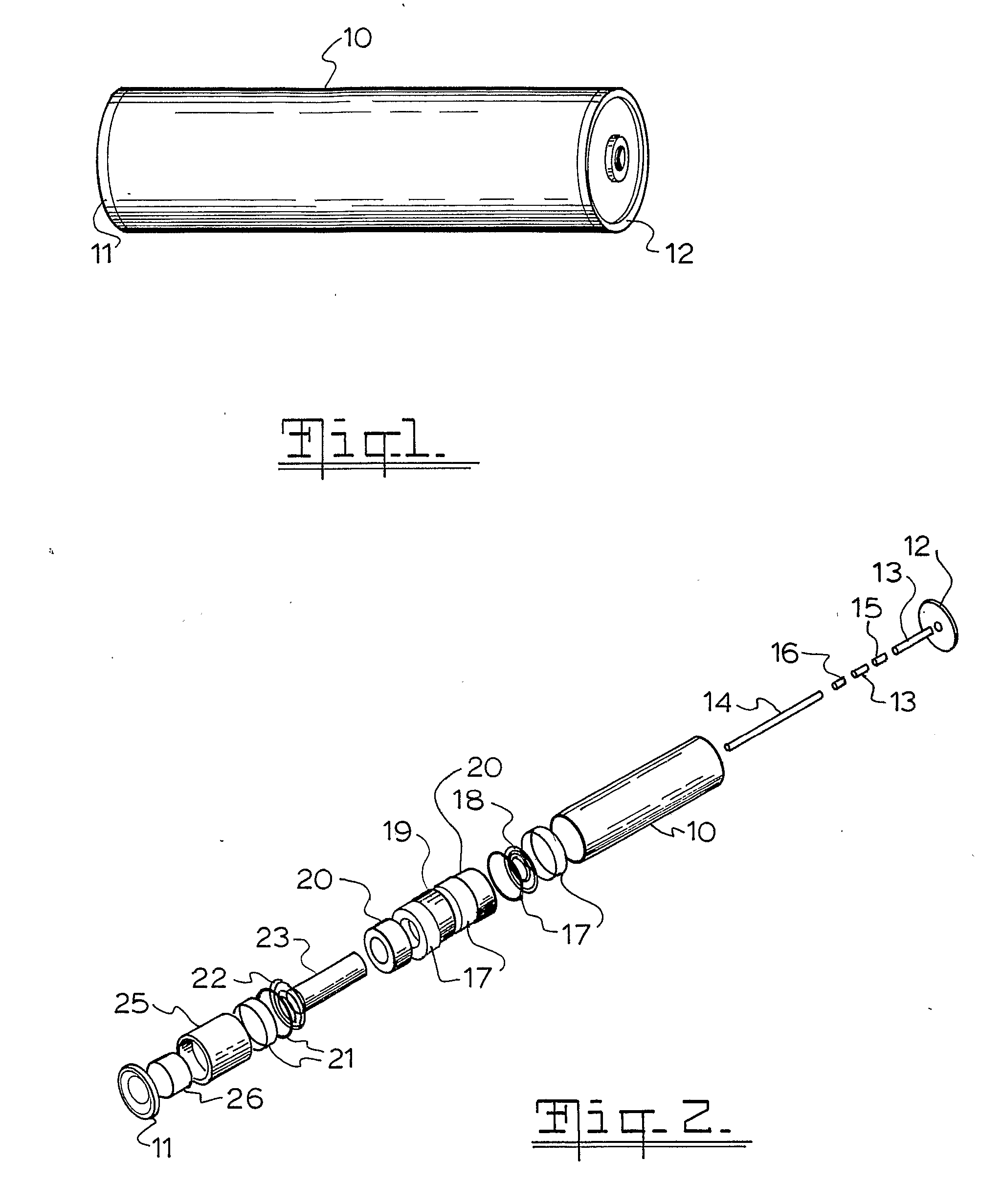
[0052] The embodiment of FIG. 2 uses a single electrical coil 23 suspended by 2 coil springs 18,22 within a pair of toroidal magnets 19,20. Electrical connection between the electrical coil and the electronics is via the coil springs 18,22. The magnets are held within the casing 10 and the end cap 11 and top cap 12. Spacers 17,21 hold the magnets in position within the casing 10. A central shaft is formed by mild steel spacers 13 and bottom axis magnet 15 and top axis magnet 16. The electronics pack 25 and the super capacitor 26 are located adjacent the end cap 11. The toroidal magnets are polarised in two directions focussing the north magnetic pole inwards in magnets 20 and focussing the north ma...

first embodiment

[0053] In the FIG. 3 embodiment three electrical coils 43 are resiliently mounted on a torsion wire 33 suspended between four permanent magnets 35, 36, 39 and 40, with a counter weight 47 mounted on the torsion wire 33, but suspended outside the permanent magnets 35,36,39,40. Electrical connection between the coils 43 and the electronics may be via the torsion wire 33. The harvested energy is stored in the storage device 46 preferably a super capacitor. Electrical connection between the coils 43 and the electronics 45 may be via the torsion wire 33. Spacer 37 keeps the vital parts in position, with the outer casing 30, the top cap 32 and end cap 31. The invention functions by the inertial capture of mechanical energy moving the masses (or single mass) connected to the coils with respect to the magnetic fields within the slots of the permanent magnets, thereby generating energy. The advantage of the torsion system is that it allows energy capture from two degrees of freedom, compared...


PUM


Abstract

An electrical generator which includes a magnetic field generated within a housing (10) by permanent magnets (19, 20) located within the housing and a coil (23) is resiliently mounted within the magnetic field such that movement of the housing induces movement of the coil to generate a current. The generator includes an electronics device (45) connected to the coil which is adapted to rectify the current and incorporating a charge storage device (46). In one embodiment, at least one coil is suspended on a torsion wire (33) within the magnetic field and the torsion wire carries a counter weight (47) whose mass is selected to resonate with the vibrational frequency to which the generator is subjected. The coils are arranged to oscillate at frequencies less than 100 Hz and are particularly useful in harvesting the motion and vibration of vehicles.

Description

[0001] This invention relates to a magnetic based electric power source as a substitute for batteries and mains power connections, that draw on ambient vibrations or motion. BACKGROUND TO THE INVENTION [0002] For some time there has been interest in harvesting energy from vibrations or motion such as walking to provide power as a replacement for batteries. Two sources of electric power have been used previously piezoelectric devices and magnetic devices. [0003] U.S. Pat. No. 3,480,808 discloses a generator in which a coil moves relative to a magnet or a magnet moves relative to a coil. [0004] U.S. Pat. Nos. 4,412,355 and 4,471,353 disclose a switch that powers a transmitter to switch on a remote light using the current generated by a magnet on a vibrating reed interacting with a coil. [0005] U.S. Pat. No. 5,347,186 discloses in part a battery replacement device using magnetically levitated magnets oscillating within coils. As a battery replacement, the electronics includes rectifier...

Claims


Application Information

Patent Timeline
Patent Type & Authority Applications(United States)
IPC IPC(8): H02K35/04H02N2/18
CPCH02K7/061H02K35/04H02K7/1876H02K7/1853
Inventor CAP, GEORGE JAROSLAV
Owner KINERGI
Why Eureka
Try Eureka