Method and system for tracking a moving station or target in free space communications

Active Publication Date: 2008-01-03
LGS INNOVATIONS
View PDF5 Cites 26 Cited by
  • Summary
  • Abstract
  • Description
  • Claims
  • Application Information

AI Technical Summary

Benefits of technology

[0005] An embodiment of the present invention relates to a method and system for target acquisition and tracking of a moving station or target (e.g., an unmanned aerial vehicle or “UAV”) for carrying out free space optical communications. For example, the UAV may be for purposes of reconnaissance and surveillance, wherein the optical link provides a secure and high-bandwidth communications pathway between the moving station and a ground station, for, e.g., transmitting real-time

Problems solved by technology

The initial process of target location and optical pointing is known as “acquisition.” The ongoing process of following the movements of the remote station over time is known as “tracking.” The problem is to design an algorithm for acquisition and tracking that increases the time during which data can be reliably transmitted between remote stations, taking into account the intervals when laser transmissions are obstructed or are disab

Method used


Image

  • Method and system for tracking a moving station or target in free space communications
  • Method and system for tracking a moving station or target in free space communications
  • Method and system for tracking a moving station or target in free space communications

Examples


Embodiment Construction

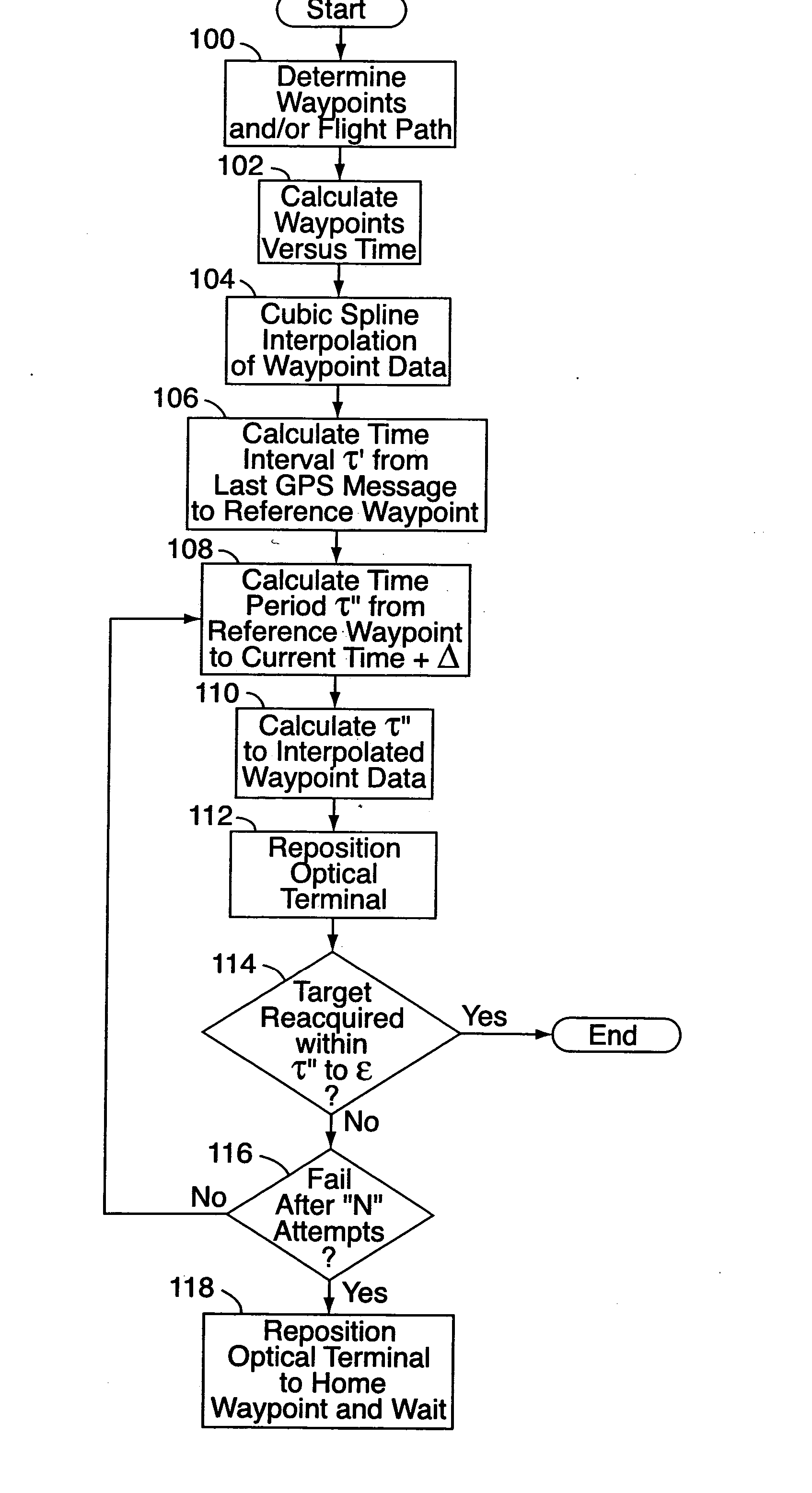
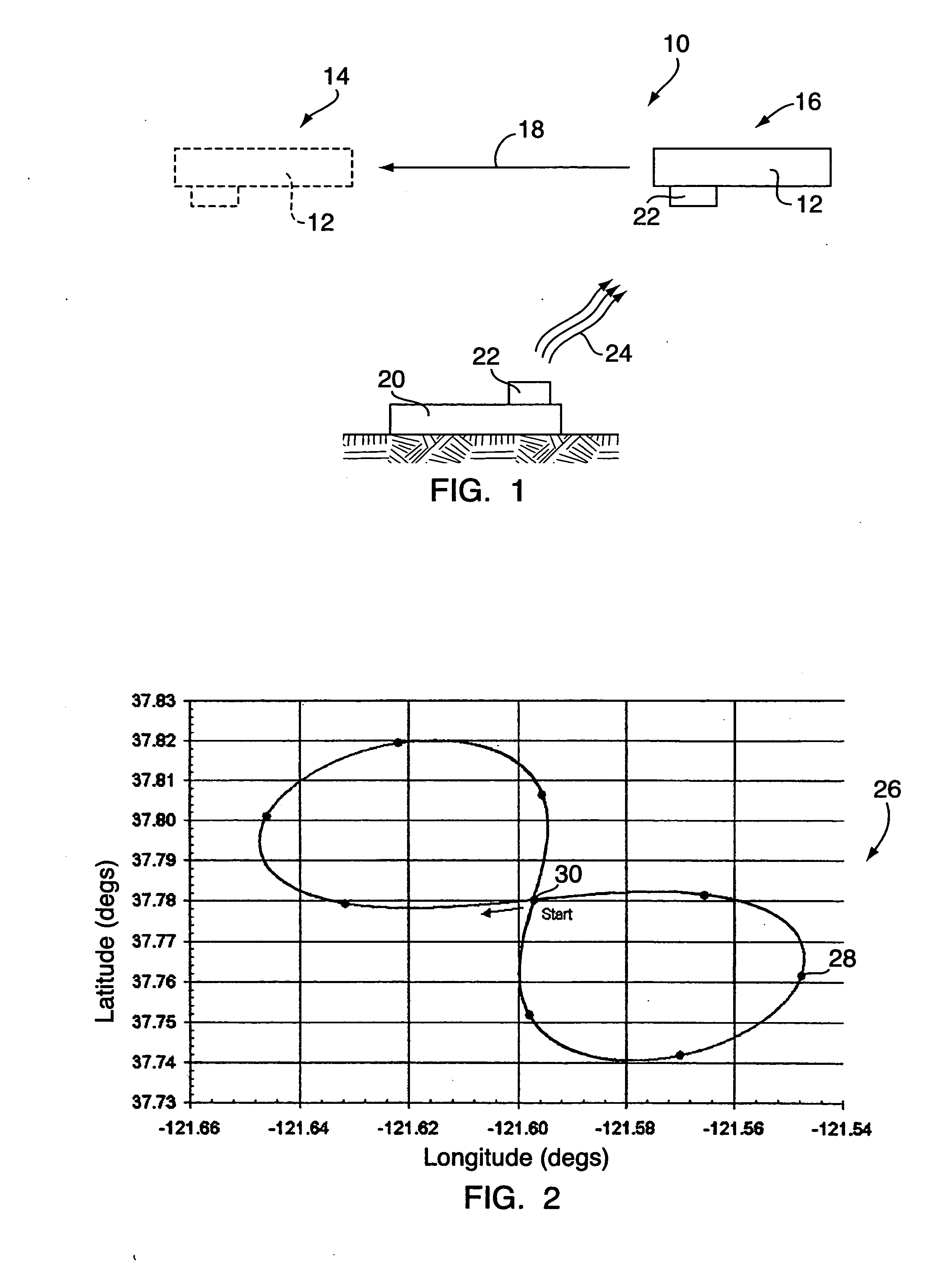
[0017] With reference to FIGS. 1-9, an embodiment of the present invention relates to a method and system 10 for tracking a moving station or target 12 for carrying out free space optical communications. The system 10 uses an “elapsed time”-based approach to determine the position 14 of the moving station 12 at any future point in time, based on the time difference since the moving station's 12 last known position 16. A mathematical model of the expected path 18 of the moving station 12 is used, which, when combined with the last known position 16 and time elements, can accurately predict the future position 14 of the moving station 12.

[0018] The tracking system 10 will most typically be used in the context of free space optical communications between first and second remote stations, e.g., the moving station or target 12 and a stationary ground station 20. Typically, the moving station 12 will be, for example, an unmanned aerial vehicle (“UAV”) that travels generally along a desig...


PUM


Abstract

A method for target acquisition and tracking of a moving station or target (e.g., an unmanned aerial vehicle) for carrying out free space optical communications uses an “elapsed time”-based approach to determine the position of the moving station at any future time, based on the time difference since the moving station's last known position. For example, the vehicle may be for purposes of reconnaissance, where the optical link provides a secure and high-bandwidth communications pathway between the moving station and a ground station. A mathematical model of the moving station's expected periodic flight path is combined with position and time elements to accurately predict the future position of the moving station for target re-acquisition. The model is a cubic spline interpolation of known flight path waypoints. The system may also employ multiple waypoints in initial acquisition, by alternating acquisition attempts over several waypoints instead of “staring” at a single waypoint.

Description

STATEMENT REGARDING FEDERALLY SPONSORED RESEARCH [0001] This invention was made with Government support. The Government has certain rights in this invention.FIELD OF THE INVENTION [0002] The present invention relates to optical communications and, more particularly, to optical communication over free space. BACKGROUND OF THE INVENTION [0003] Free space optical communications involve using light to transmit data across the open distance between two points, in a line-of-sight manner, and without the use of an optical waveguide or other medium. Typically, transmissions are made through the atmosphere or in space / vacuum using a laser system, or, in some short-distance cases, LED's or the like. For a laser communication system, encoded binary data is transmitted using modulated laser beams that travel from the sending station to the receiving station. In the case where one or both of the stations are in motion, e.g., an aircraft and a ground terminal, satisfactory transmission relies on ...

Claims


Application Information

Patent Timeline
IPC IPC(8): G01C1/00
CPCG01C21/005
Inventor ROMAIN, DENNIS M.TRACHTENBERG, ROBERT D.
Owner LGS INNOVATIONS
Why Eureka
Try Eureka