Multicast network monitoring method and multicast network system to which the method is applied

a network monitoring and multicast technology, applied in the field of multicast network monitoring methods and multicast network systems, can solve problems such as delay in detection of failures, intervals of sending ping, and content providers cannot know the occurrence of failures

Inactive Publication Date: 2008-01-03
FUJITSU LTD
View PDF4 Cites 59 Cited by
  • Summary
  • Abstract
  • Description
  • Claims
  • Application Information

AI Technical Summary

Benefits of technology

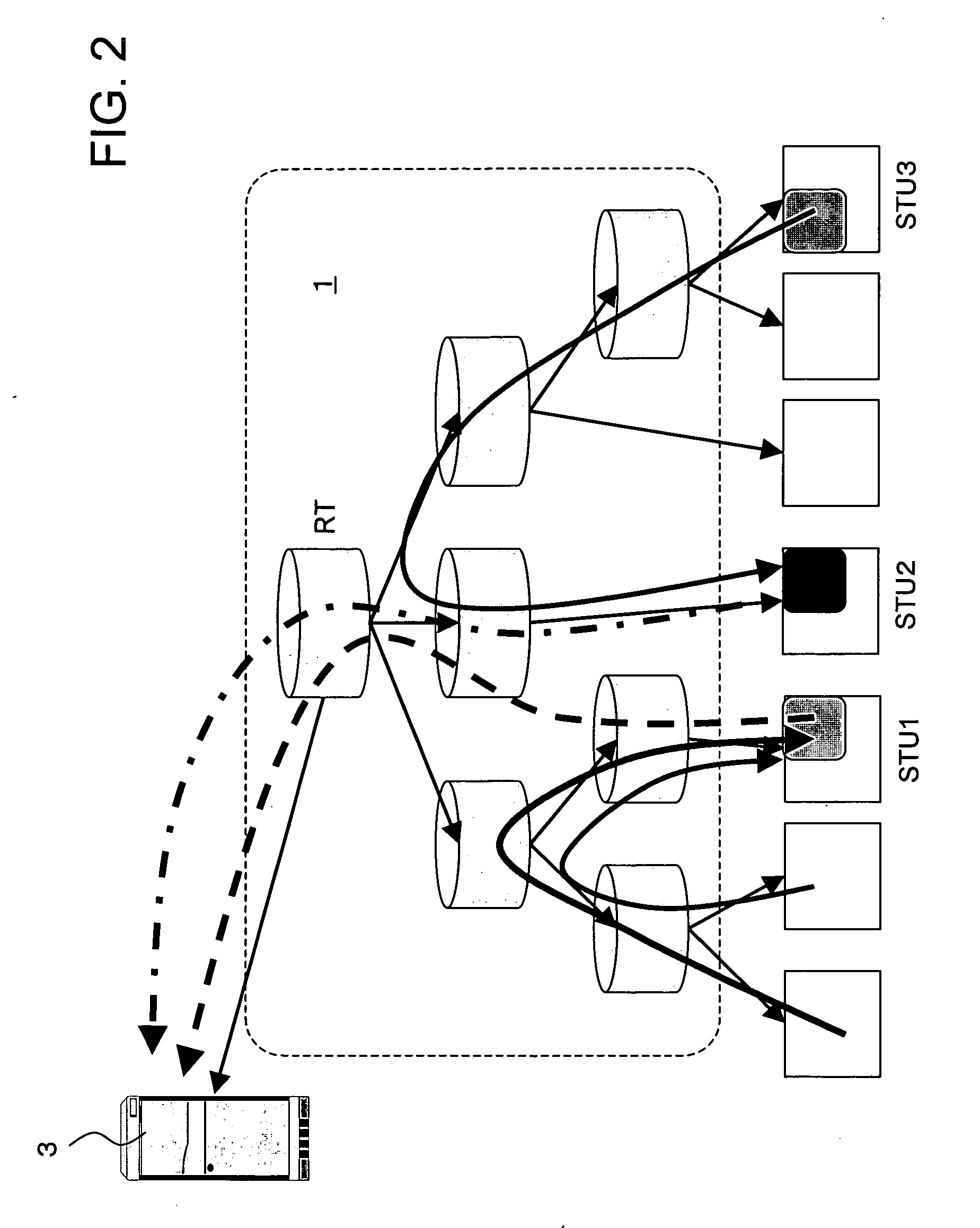
[0047]By determining a failure with the features of the present invention based on the number of acknowledgments from the acknowledgment agents in the multicast network, if a large-scale failure occurs, the failure can be detected quickly. By narrowing down the area and performing the acknowledgment request process again, candidates for the failure point can be extracted more accurately, and an operation such as failure recovery can be started quickly.

Problems solved by technology

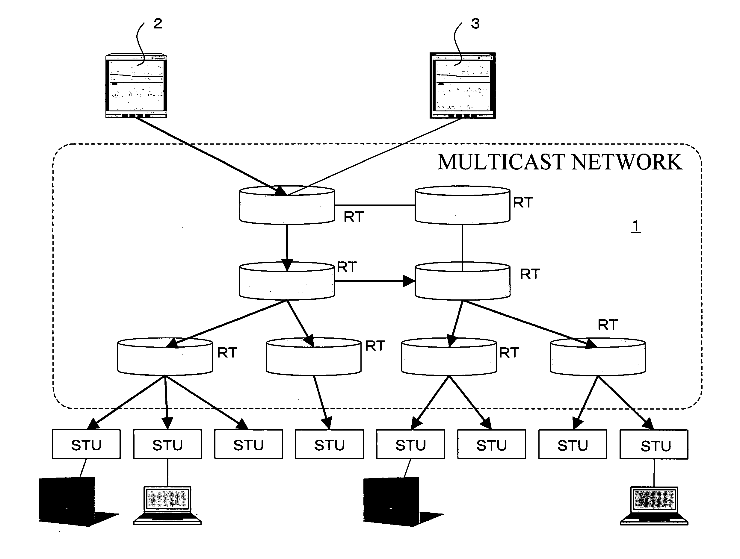
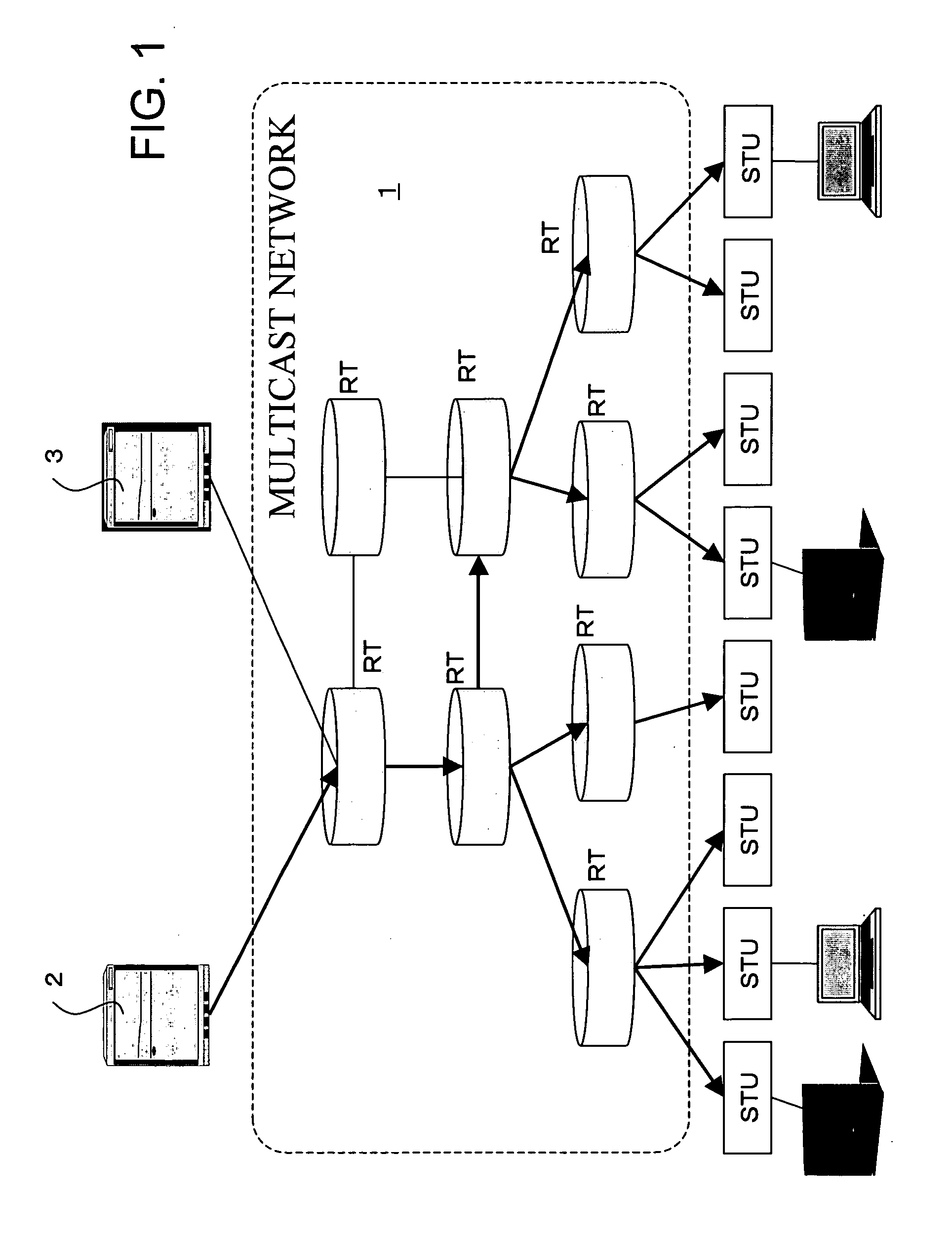
Therefore, if a failure occurs in the multicast network 1, a sender, especially, a content provider cannot know the occurrence of the failure.
Therefore, if a large number of terminals exist, intervals of sending the ping to one terminal are increased due to a server load, and it is problematic that detection of a failure is delayed.
Since the ICMP Ping is not distributed with the multicast mechanism (e.g., the ping may arrive at the terminal STU via a different path), it is problematic that the ICMP Ping is essentially inadequate for the communication monitoring of the multicast network 1.
However, in this ACK aggregation mode, if the terminals increase, more aggregation servers are needed, and it is problematic that implosion occurs in time-out notifications from aggregation servers.
Although a plurality of monitoring modes are proposed as described above, it is difficult in any case to detect network communication disconnection that may affect a multiplicity of users in a large-scale multicast network.

Method used


Image

  • Multicast network monitoring method and multicast network system to which the method is applied
  • Multicast network monitoring method and multicast network system to which the method is applied
  • Multicast network monitoring method and multicast network system to which the method is applied

Examples


first embodiment

[0064]FIG. 4 is an operation flow of a first embodiment of the present invention corresponding to FIG. 3. Description will be made of an operation example of the multicast network system with reference to FIG. 4.

[0065]In FIG. 4, I is an operation flow portion for the monitoring server 3 and II is an operation flow portion for the acknowledgment agent.

[Monitoring Server's Process I]

[0066]In the monitoring server 3, an acknowledgment probability / acknowledgment area determining unit 30 accepts an activation request from a system administrator along with arguments, which are an acknowledgment probability, the number of agents, the number of acknowledgment messages used as a determination threshold, a transmission / determination interval, and a monitoring group address (step S11).

[0067]For example, it is assumed that the arguments of the activation request are the acknowledgment probability of 5%, the number of agents of 10,000, the determination threshold x (=450) for the expected number...

second embodiment

[0088]A second embodiment is most appropriate when a system administrator, etc., want to know a situation / abnormality in a certain area. The determination accuracy can be improved by narrowing down a certain area.

[0089]FIG. 7 is an operation flow of the second embodiment and the operation of the embodiment will be described with reference to FIG. 7.

[Monitoring Server's Process I]

[0090]In the monitoring server 3, the acknowledgment probability / acknowledgment area determining unit 30 accepts an activation request from the system administrator along with arguments, which are an acknowledgment probability, an acknowledgment area identifier, the number of agents in the acknowledgment area, the number of acknowledgment messages used as a determination threshold, a transmission / determination interval, and a monitoring group address (step S11).

[0091]For example, it is assumed that the arguments of the activation request are the acknowledgment probability of 5%, the number of agents in the a...

third embodiment

[0109]A feature of a third embodiment is intended to improve the determination accuracy by eliminating the acknowledgment messages belated for some reason.

[0110]Among the functional blocks of the monitoring server 3 and the acknowledgment agent STU shown in FIG. 3, the relationships in process procedures are the same as the preceding embodiments and, therefore, description correlated with these functional blocks is omitted in the following description of the embodiment.

[0111]The process of the third embodiment can be described with reference to the operation flow shown in FIG. 4, which is used in the description of the first embodiment.

[Monitoring Server's Process]

[0112]The process of the monitoring server 3 will be described.

[0113]An activation request is accepted from the system administrator along with arguments, which are an acknowledgment probability, an acknowledgment area identifier, the number of agents in the acknowledgment area, the number of messages used as a determinati...


PUM


Abstract

Disclosed is a multicast network system including a multicast network which provides a plurality of relay nodes, and a monitoring server and a plurality of acknowledgment agents connected to the multicast network. The monitoring server includes an acknowledgment request message generating and sending unit that generates and sends an acknowledgment request message storing an acknowledgment probability to the plurality of acknowledgment agents; a collecting unit that collects acknowledgment messages from acknowledgment agents; and a collection number comparing unit that compares the number of acknowledgment messages collected by the acknowledgment message collecting unit with the expected number of acknowledgment messages obtained from the acknowledgment probability and the total number of acknowledgment agents. The acknowledgment agent has an acknowledgment message sending unit that determines whether an acknowledgment is needed for the acknowledgment request message based on the acknowledgment probability stored in the acknowledgment request message to send an acknowledgment message.

Description

CROSS-REFERENCE TO RELATED APPLICATIONS[0001]This application is based upon and claims the benefit of priority from the prior Japanese Patent Application No. 2006-180031, filed on Jun. 29, 2006, the entire contents of which are incorporated herein by reference.BACKGROUND OF THE INVENTION[0002]1. Field of the Invention[0003]The present invention relates to a multicast network monitoring method and a multicast network system to which the same is applied.[0004]2. Description of the Related Art[0005]A multicast network means a network that performs a so-called push type operation of copying and distributing a packet to other terminals in the same group when one terminal in a group including a plurality of terminals transmits the packet to the network.[0006]FIG. 1 shows a configuration example of a multicast network system with a multicast network function, which is used for providing services such as IPTV or remote lectures. In FIG. 1, a multicast network 1 includes a plurality of relay...

Claims


Application Information

Patent Timeline
Patent Type & Authority Applications(United States)
IPC IPC(8): H04J1/16H04L12/56H04L12/70
CPCH04L12/1868H04N21/6437H04N21/6405
Inventor UENO, HITOSHI
Owner FUJITSU LTD
Why Eureka
Try Eureka