Method of constructing a secondary containment area

a technology of containment area and secondary containment area, which is applied in the field of above ground tanks, can solve problems such as environmental toxicity

Inactive Publication Date: 2008-01-03
ASSET GUARD PROD INC
View PDF11 Cites 22 Cited by
  • Summary
  • Abstract
  • Description
  • Claims
  • Application Information

AI Technical Summary

Benefits of technology

[0008]The present invention is thus directed to an improved method for building the secondary containment structure for an AST. The preferred embodiment of the present invention involves leveling the AST site, laying a

Problems solved by technology

Produced water with a high concentration of impurities can be corrosive to th

Method used


Image

  • Method of constructing a secondary containment area
  • Method of constructing a secondary containment area
  • Method of constructing a secondary containment area

Examples


Embodiment Construction

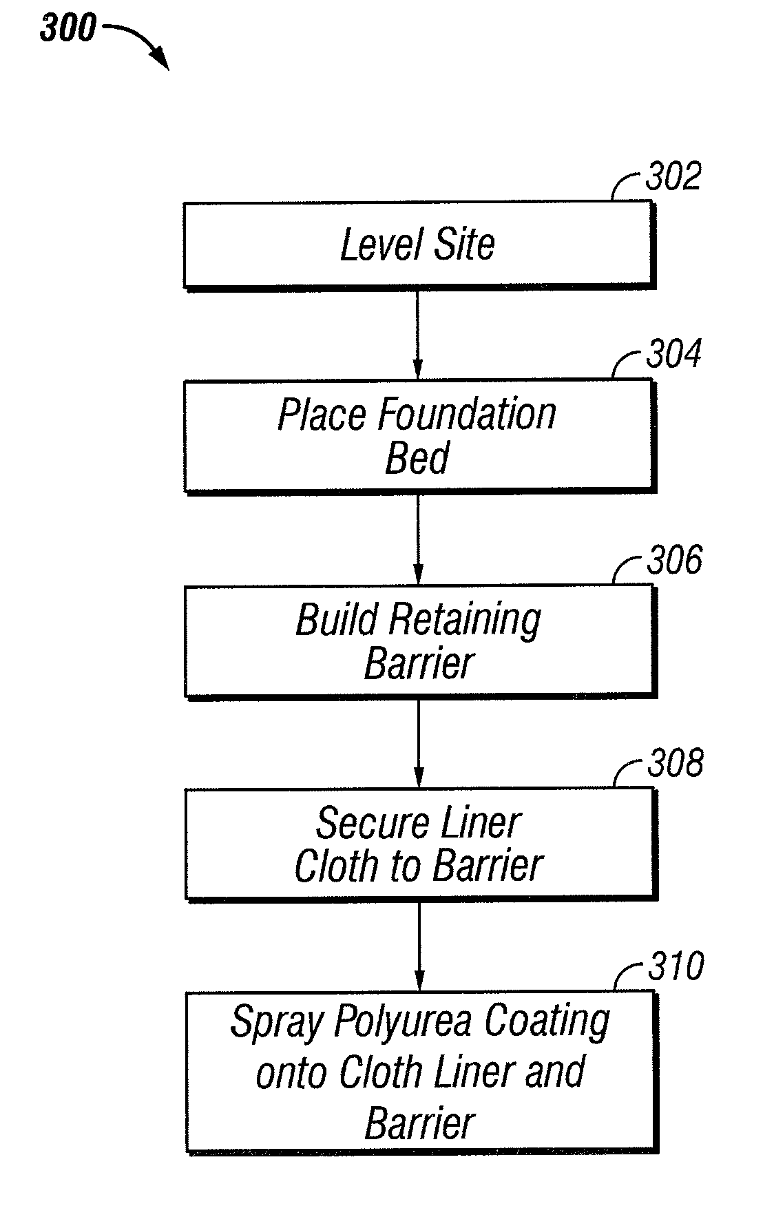
[0018]The present invention involves an improved method for constructing the secondary containment area for one or more above ground storage tanks (ASTs). The invention produces an effective, inexpensive, versatile secondary containment area for ASTs.

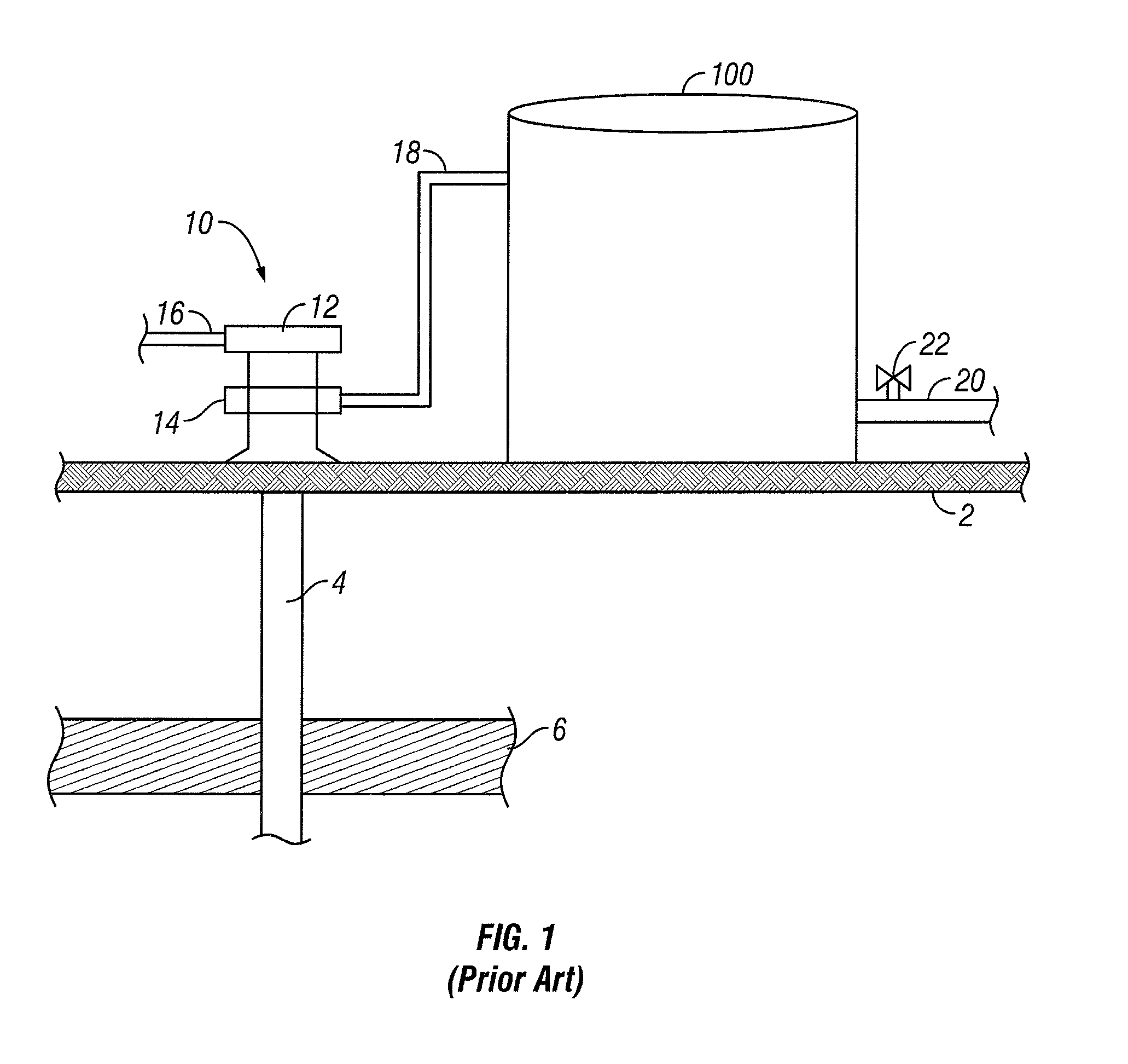
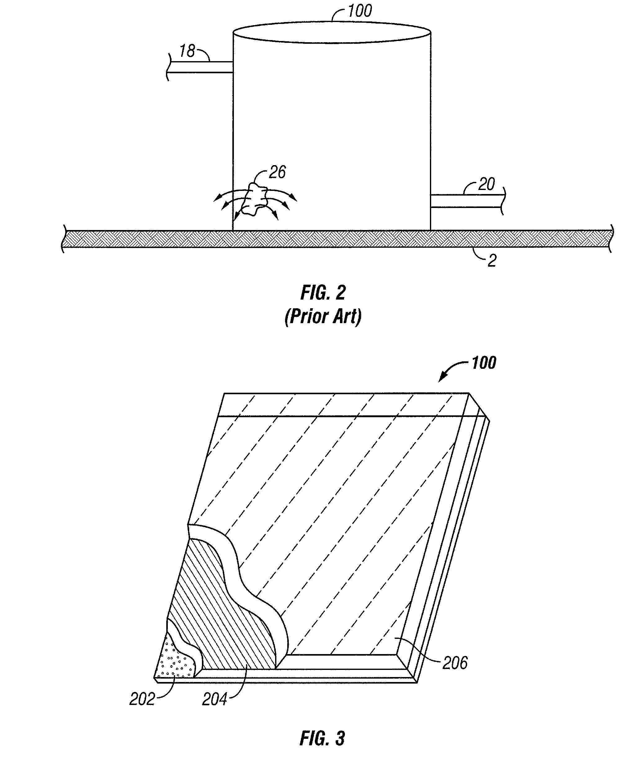
[0019]Referring initially to FIG. 1, the reference numeral 100 refers in general to an AST, which has an inlet stream 18, an outlet stream 20 and a valve 22 (or its equivalent) for manipulating the flow rate of the outlet stream (collectively referred to as the “ancillary piping”). The produced water flowing through the ancillary piping and stored in the AST 100 can be highly corrosive and, if released into the environment, can contaminate ground water in the area. The claimed invention is thus directed towards a method of constructing a secondary containment area to collect any spillage or leakage from an AST.

[0020]Even though FIG. 1 shows a cylindrical AST with its axis oriented perpendicular the ground 2, one skilled in the art knows...


PUM


Abstract

The method of the present invention results in a secondary containment area for above ground storage tanks. The method involves leveling the site, laying a foundation bed, building a retaining barrier around the site, covering the foundation bed and retaining barrier with a liner cloth, and applying a layer of polyurea to the liner cloth and retaining barrier.

Description

BACKGROUND OF THE INVENTION[0001]1. Technical Field of the Invention[0002]The present invention relates generally to above ground tanks that are used in the oil and gas industry to store fluids produced from underground hydrocarbon bearing formations, and more particularly to an improved method and an improved apparatus for containing spills or leaks from the above ground tanks so that such spills or leaks can be recovered or removed and disposed of properly before the environment is contaminated.[0003]2. Description of the Related Art[0004]During the production of oil or gas from an underground well, it is common for water to be produced along with the oil or gas. This water, called “produced water”, is typically separated from the oil or gas at the well site and temporarily stored in above ground storage tanks (ASTs). The produced water varies in quality from one well to the next, and it can have high quantities of minerals, salts, oil, gas, sand and other substances dissolved, mi...

Claims


Application Information

Patent Timeline
IPC IPC(8): E02B7/00
CPCB65D90/24Y10T137/0318
Inventor PERKINS, LARRY L.
Owner ASSET GUARD PROD INC
Why Eureka
Try Eureka