Metallic mini hooks for joining of metallic and composites

a technology of metallic and composite materials, applied in the field of structural joints, can solve the problems of high installation time of the joining method, inability to meet the requirements of the construction process, so as to reduce the installation time of fasteners to secure composite materials and metallics, enhance the mechanical bond, and enhance the mechanical bond

Inactive Publication Date: 2008-01-03
LOCKHEED MARTIN CORP
View PDF1 Cites 103 Cited by
  • Summary
  • Abstract
  • Description
  • Claims
  • Application Information

AI Technical Summary

Benefits of technology

[0006]Embodiments of the present invention provide a method for joining a first composite structural member and a metallic substrate is provided. This method involves drawing projections from a metallic substrate using a Co-Meld or other like process. Individual plies of composite materials are laid upon the metallic substrate and projections. These projections penetrate the individual ply or layers of the composite material. A mechanical feature that serves as a retaining device may be located at the distal end of the projections in order to prevent separation, or pull out failure, of the composite materials from the metallic substrate. During formation, the composite materials may be pre-impregnated with resin or in the form of a dry fabric which is later infused with a resin or other material to complete the formation of the composite material. Additionally, other layers of composite material may be placed over the mechanical features located at the distal ends.
[0007]In this way, the sheer strength of the bond between the composite material and the metallic substrate is greatly enhanced or reinforced through the use of projections which are typically oriented normally to the metallic substrate surface. This allows a three dimensional joint between the metallic substrate and the composite material to be formed as opposed to a traditional two dimensional interface. This strength benefit is inherit in the co-meld reinforcement technology.
[0008]The embodiment of the present invention provides a structural member that includes a metallic substrate on which a composite material is fastened. As with co-meld, this metallic substrate has a number of projections substantially oriented normal to the surface of the metallic substrate. These projections penetrate the individual layers of the composite material laid up on the metallic substrate. To further enhance the mechanical bond between the metallic substrate and the composite material, a retaining device such as a cap or deformation located at the distal end of the projection. This may be an end cap or button, hook, or other like deformation of the projection. This projection serves to retain the composite material at the proximate to the metallic substrate.
[0009]Embodiments of the present invention provide several distinctive advantages. First, the tooling associated with drilling holes and installing fasteners to secure composites and metallics is greatly reduced. Additionally, non-conformances may also be reduced as the composite material is laid up on the metallic substrate. Improvements in pull off strength as compared to traditionally bonded joints and standard Co-Meld joints is observed as the composite is held by retaining mechanical feature to the metallic substrate. Improved performance of the joint is realized without many of the drawbacks associated with traditional fasteners. For example, no drilling of the metallic substrate is required, part count is reduced, and a fully flush outer mold line may result.

Problems solved by technology

This joining method also requires significant setup time in drilling holes and installing fasteners to attach the members to one another.
Such holes often produce localized stresses and mechanical loads that the structure must account for.
Furthermore, quality assurance issues may arise when installing such fasteners (misdrilled holes and improper fastener installation is common).

Method used


Image

  • Metallic mini hooks for joining of metallic and composites
  • Metallic mini hooks for joining of metallic and composites
  • Metallic mini hooks for joining of metallic and composites

Examples


Embodiment Construction

[0017]Embodiments of the present invention are illustrated in the FIGUREs, like numerals being used to refer to like and corresponding parts of the various drawings.

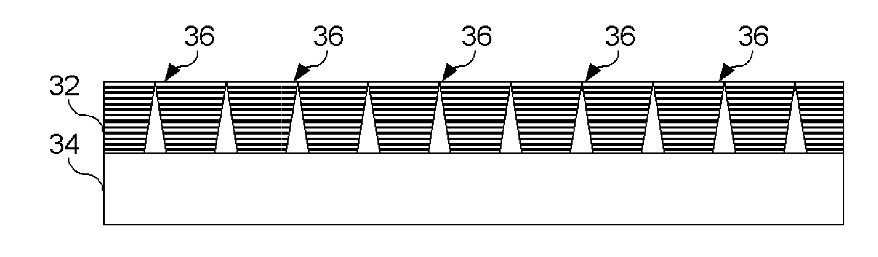
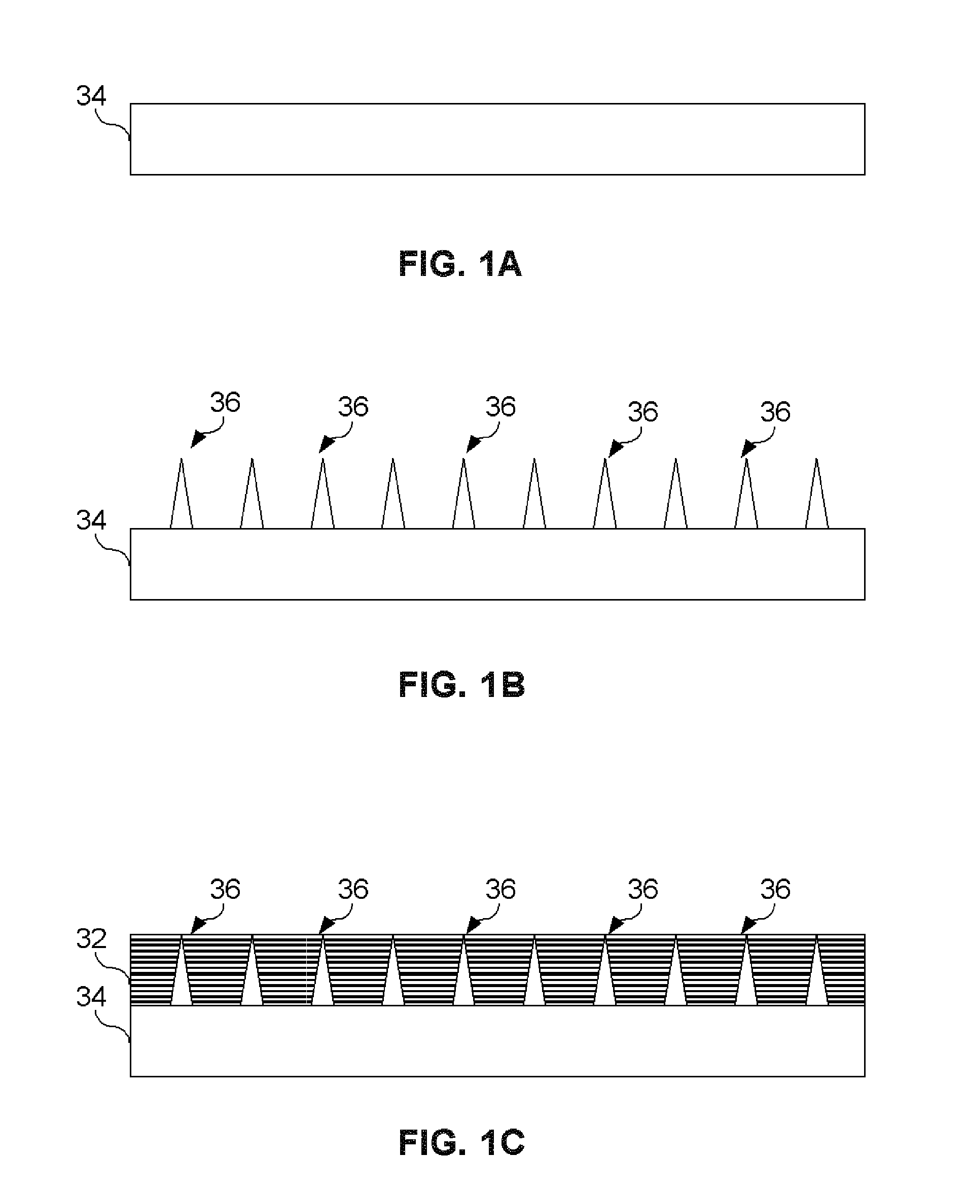
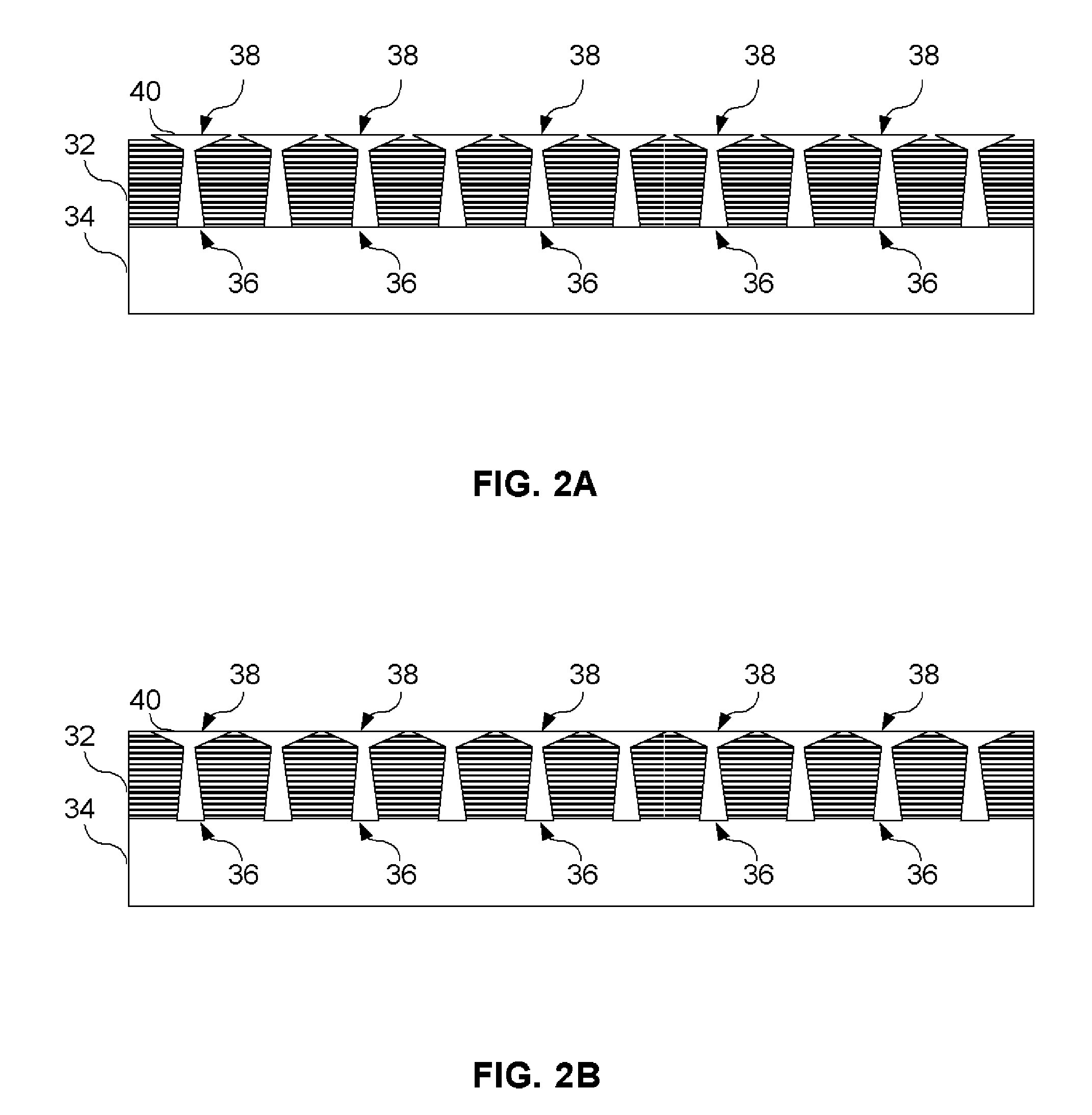
[0018]Embodiments of the present invention provide a method for joining a composite structural member and a metallic substrate is provided. This method involves drawing projections from a metallic substrate using a Co-Meld or other like process. Individual plies of composite materials may be laid upon the metallic substrate and projections. These projections penetrate the individual ply or layers of the composite material. A mechanical feature that serves as a retaining device is located at the distal end of the projections in order to prevent separation, or pull out failure, of the composite materials from the metallic substrate. During fabrication, the composite materials may be pre-impregnated with resin or in the form of dry fabric which is later infused with a resin or other material to complete the formation of the...


PUM

PropertyMeasurementUnit
metallicaaaaaaaaaa
mechanical featureaaaaaaaaaa
mechanicalaaaaaaaaaa

Abstract

A method for joining a first structural member and a metallic substrate is provided. This method involves drawing projections from a metallic substrate using a Co-Meld or other like process. Individual plies of composite materials may be laid upon the metallic substrate and projections. These projections penetrate the individual ply or layers of the composite material. A mechanical feature that serves as a retaining device may be located at the distal end of the projections in order to prevent separation of the composite materials from the metallic substrate. The composite materials may be infused with a resin or other material to complete the formation of the composite material. Additionally, other layers of composite material may be placed over the mechanical features located at the distal ends.

Description

TECHNICAL FIELD OF THE INVENTION[0001]The present invention relates generally to structural joints and more particularly a method to join two or more members.BACKGROUND OF THE INVENTION[0002]Structural joints in aircraft applications frequently involve the joining of metallic and composite structures. These joints are accomplished using typical fastening concepts which suffer from significant strength reductions caused by the need to drill holes in the metallic member. This joining method also requires significant setup time in drilling holes and installing fasteners to attach the members to one another. Such holes often produce localized stresses and mechanical loads that the structure must account for. To account for such localized loads, the structures are typically reinforced resulting in increased weight and loads to be handled by the structure. Furthermore, quality assurance issues may arise when installing such fasteners (misdrilled holes and improper fastener installation is...

Claims


Application Information

Patent Timeline
Patent Type & Authority Applications(United States)
IPC IPC(8): B32B3/06
CPCB29C65/562B29C65/564B29C66/721B29C66/742B29C70/885B29L2031/3076Y10T428/24008B29C65/64B29C66/1122B29C66/21B29C66/30321B29C66/45F16B5/07B29C66/72141
Inventor BARNES, JOHN E.KOON, ROBERT W.OLLIFFE, ROBERT J.ENGELSTAD, STEPHEN P.
Owner LOCKHEED MARTIN CORP
Why Eureka
Try Eureka