Heat Treatment Furnace and Heat Treatment Facility Comprising It

a heat treatment furnace and heat treatment facility technology, applied in the field of heat treatment, can solve the problems of reducing the life expectancy of equipment, reducing the cost of disposing of fast heat-up furnaces, and reducing the efficiency of heat-up and cooling trays, so as to reduce the cost of cooling and heating. the effect of reducing the cost of cooling and heating, and reducing the cost of heat-up and cooling

Active Publication Date: 2008-01-03
TOYOTA JIDOSHA KK +1
View PDF2 Cites 13 Cited by
  • Summary
  • Abstract
  • Description
  • Claims
  • Application Information

AI Technical Summary

Benefits of technology

[0021] According to the present invention, a hot-air circulation equipment, which circulates hot air in the furnace chamber along peripheral direction when viewed in plan, is provided in the furnace chamber. Accordingly, the amount of heat air (energy) supplied to each of the mounting shelves is equalized and each of the work pieces is heat-treated uniformly, thereby equalizing the product quality of the work pieces. Falling sand is not blown up so that the life expectancy of the equipment is extended.
[0022] According to the present invention, with regard to a heat treatment furnace, a furnace chamber of the heat treatment furnace comprises a furnace body opening downward and a floor body closing the lower opening of the furnace body, the furnace chamber is divided into upper and lower two spaces by a partition, the upper space is constructed as an ageing furnace performing ageing treatment, the lower space is constructed as an solution furnace performing solution treatment, one or plural stages of mounting shelves on which a work piece is mounted are provided each of the ageing furnace and the solution furnace, and the furnace body is provided therein with a hot-air circulation equipment circulating hot air in the ageing furnace along peripheral direction when viewed in plan and a hot-air circulation equipment circulating hot air in the solution furnace along peripheral direction when viewed in plan. Accordingly, the present invention requires smaller space for installing the heat treatment furnace (the equipment is miniaturized), whereby the space for installing the whole heat treatment facility is reduced.
[0023] According to the present invention, the floor body is rotatively driven, and the mounting shelf is supported by a prop standingly provided on the floor body and is rotated integrally with the floor body. Accordingly, the influence of unevenness of heat transfer amount caused by difference of disposition is reduced, thereby equalizing the product quality of the work pieces.
[0024] According to the present invention, the floor body is provided therein with a chute part communicated with outer space below the floor body and a sand discharge mechanism having a lid opening and closing lower opening of the chute part, and a guide member opening and closing the lid and a sand recovery box into which sand accumulated on the lid is thrown at the time that the lid is opened are provided below the floor body. Accordingly, the equipment recovering sand is easy and cheap. Also, sand can be recovered easily.
[0025] According to the present invention, the heat treatment furnace is used as a solution furnace and an ageing furnace, and heat treatment facility comprises the solution furnace and the ageing furnace. Accordingly, compared with the heat treatment furnace of the conventional construction, the time for finishing the solution treatment by the solution furnace and the ageing treatment by the ageing furnace is shortened, whereby the all processes of the heat treatment is finished for a short time. Compared with the conventional facility using trays, the execution cost is reduced, the execution period is shorten, and the maintenance cost is reduced. The solution furnace and the ageing furnace are constructed individually so that the facility can be transferred and diverted easily. The number of the burner and fan is reduced and the conveying equipment for the trays is not necessary.
[0026] According to the present invention, the heat treatment facility comprises the solution furnace heat-treating work pieces, a quenching bath quenching the work pieces solution-treated by the solution furnace, the ageing furnace ageing the work pieces quenched by the quenching bath, an air cooling equipment cooling the work pieces aged by the ageing furnace, a work piece take-in equipment taking in the work pieces to be solution-treated by the solution furnace, a work piece take-out equipment taking out the work pieces cooled by the air cooling equipment, and a robot arm moving the work pieces one by one to the work piece take-in equipment, the solution furnace, the quenching bath, the ageing furnace, the air cooling equipment and the work piece take-out equipment in this order. Accordingly, work pieces complicated shaped and work pieces with core sand, which cannot be conveyed by a conveyor or the like, also can be conveyed by the robot arm. The quenching bath cools the work pieces one by one so that the quenching bath can be constructed compactly. The work pieces after heat-treated are cooled compulsorily by the air cooling equipment so that the work pieces can be checked easily by hand at the later process.

Problems solved by technology

With regard to the art disclosed in the above-mentioned patent literature, a fast heat-up furnace is required to be disposed, that is, the cost for disposing the fast heat-up furnace is required.
The loss of energy caused by heat-up and cooling of the trays is curtailed.

Method used


Image

  • Heat Treatment Furnace and Heat Treatment Facility Comprising It
  • Heat Treatment Furnace and Heat Treatment Facility Comprising It
  • Heat Treatment Furnace and Heat Treatment Facility Comprising It

Examples


embodiment 1

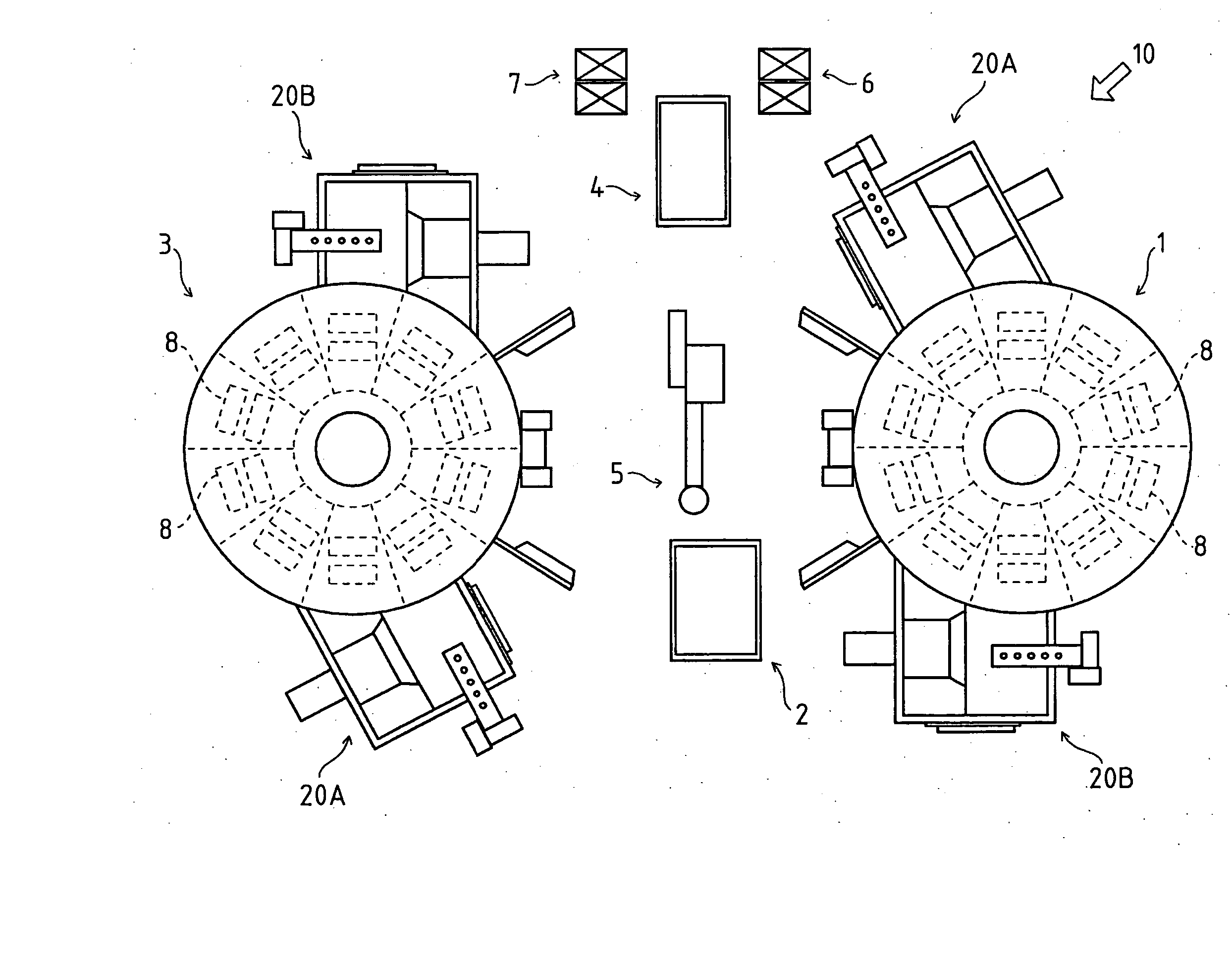
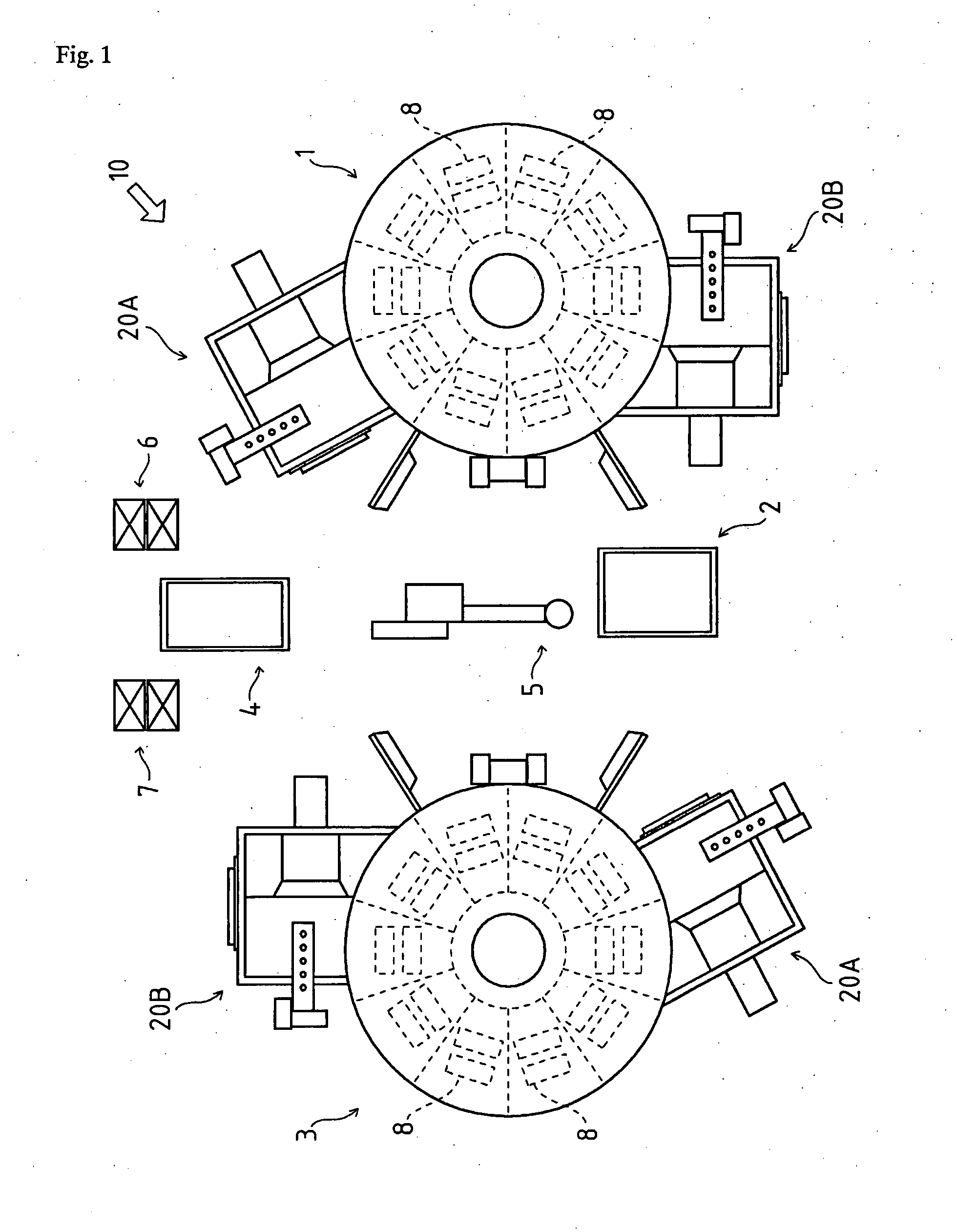
[0038] As shown in FIG. 1, heat treatment facility 10 comprises a solution furnace 1, a quenching bath 2, an ageing furnace 3, an air cooling equipment 4, a robot arm 5, a work piece take-in equipment 6, and a work piece take-out equipment 7. With regard to this construction of equipments, work pieces 8 taken in by the work piece take-in equipment 6 is solution-processed by the solution furnace 1, quenched by the quenching bath 2, aged by the ageing furnace 3, and cooled by the air cooling equipment 4 in this order, and then taken out by the work piece take-out equipment 7.

[0039] The solution furnace 1 and the ageing furnace 3 are constituted by a heat treatment furnace according to the present invention. With regard to below construction of the heat treatment furnace, one of solution treatment and ageing treatment can be performed alternatively by setting temperature and time of heat treatment.

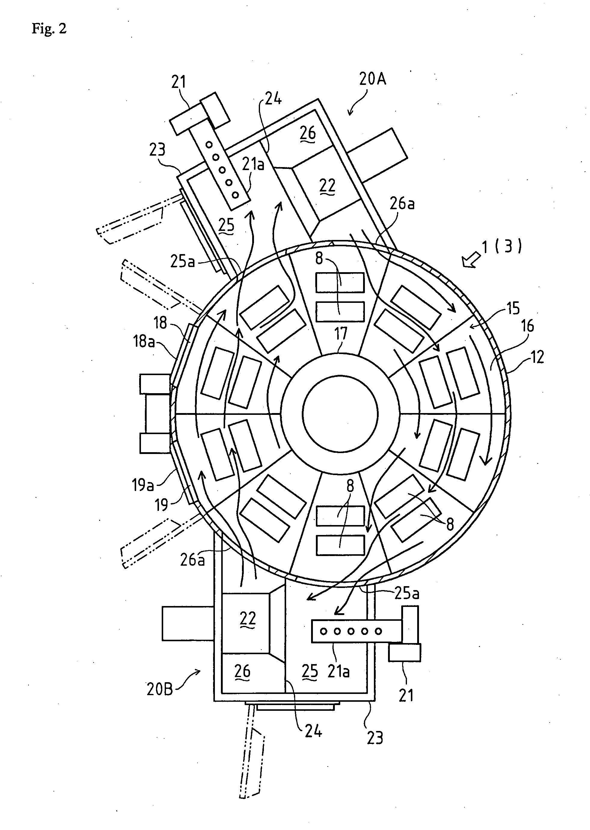
[0040] As shown in FIGS. 2 and 3, the heat treatment furnace according to the present i...

embodiment 2

[0059] As shown in FIG. 7, with regard to a heat treatment furnace 40 in this embodiment 2, the furnace chamber 15 of the furnace body 12 is divided into upper and lower two spaces by a partition 41 provided horizontally. The upper space is constructed as an ageing furnace chamber 42 for the ageing treatment, and the lower space is constructed as a solution furnace chamber 43 for the solution treatment. One or plural stages of mounting shelves 46 are provided in each of the ageing furnace chamber 42 and the solution furnace chamber 43. The furnace body 12 comprises a hot-air circulation equipment 44 circulating hot air in the ageing furnace chamber 42 along the peripheral direction when viewed in plan and comprises a hot-air circulation equipment 45 circulating hot air in the solution furnace chamber 43 along the peripheral direction when viewed in plan.

[0060] In this construction, the solution furnace chamber 43 is disposed below the ageing furnace chamber 42. That is because core...


PUM

PropertyMeasurementUnit
perimeteraaaaaaaaaa
temperatureaaaaaaaaaa
internal stressaaaaaaaaaa

Abstract

With regard to a heat treatment furnace (a solution furnace 1 and an ageing furnace 3), a furnace chamber 15 comprises a furnace body 12 opening downward and a floor body 14 closing the lower opening of the furnace body 12 and rotatably driven, and one or plural stages of mounting shelves 16 on which work pieces 8 are mounted are provided in the furnace chamber 15. Hot-air circulation equipments 20A and 20B circulating hot air in the furnace chamber 15 along the peripheral direction when viewed in plan are provided in the furnace body 12. The mounting shelves 16 are fixed to a prop 17 standingly provided on the floor body 14 and are rotated integrally with the floor body 14.

Description

FIELD OF THE ART OF THE INVENTION [0001] The present invention relates to an art of heat treatment of mold goods formed from aluminum alloy or the like by casting, forging or the like. In more detail, the present invention relates to a heat treatment furnace performing solution treatment and ageing treatment, and heat treatment facility having the heat treatment furnace. BACKGROUND ART [0002] Conventionally, there is well known heat treatment facility for castings and forgings of aluminum, steel or the like which performs a series of treatments, solution treatment, quenching treatment and ageing treatment. [0003] For example, with regard to construction of facility shown in FIG. 9, plural work pieces (treated bodies) are housed in a tray 70, and each of the work pieces in the tray 70 is solution-treated, quenched and aged continuously while conveying the tray 70. Such an art concerning heat treatment process using the tray 70 is known. [0004] With regard to the construction shown in...

Claims


Application Information

Patent Timeline
Patent Type & Authority Applications(United States)
IPC IPC(8): F27D5/00C21D1/00C21D1/34C22F1/04F27B9/02F27B9/10F27D7/04F27D25/00
CPCC21D1/00C21D9/0037C22F1/04F27B9/39F27B9/16F27B9/38F27B9/025
Inventor TAKANO, KAZUHIDEGOTO, SHINJI
Owner TOYOTA JIDOSHA KK
Why Eureka
Try Eureka