Vibratory fluidized bed reactor for continuous production of rare earth fluorides and production method

A fluidized bed reactor, rare earth fluoride technology, applied in chemical instruments and methods, rare earth metal compounds, inorganic chemistry, etc., can solve the problem of difficulty in ensuring uniformity of rare earth fluoride, low production process efficiency, large gas diffusion resistance, etc. problems, to achieve the effect of optimizing the gas-solid fluidization reaction process, improving production efficiency and reducing process costs

Inactive Publication Date: 2014-10-08
CHANGSHA RES INST OF MINING & METALLURGY
View PDF5 Cites 11 Cited by
  • Summary
  • Abstract
  • Description
  • Claims
  • Application Information

AI Technical Summary

Problems solved by technology

The control step of the rare earth oxide fluorination reaction is the internal and external diffusion process, but the average particle size of the industrially produced rare earth oxide is very small (2-11 μm), so the gaps between the particles are also small, and the bed is static, resulting in gas diffusion resistance Therefore, the mass transfer and heat transfer effects of the reaction process are very poor, and the quality of the prepared rare earth fluoride is difficult to ensure uniformity, so the packing height of the general fixed bed rarely exceeds 40mm
In addition, the heating and cooling time of the heating furnace is long, resulting in a production cycle ranging from more than ten hours to forty hours, resulting in low efficiency and high energy consumption in the production process

Method used


Image

  • Vibratory fluidized bed reactor for continuous production of rare earth fluorides and production method
  • Vibratory fluidized bed reactor for continuous production of rare earth fluorides and production method
  • Vibratory fluidized bed reactor for continuous production of rare earth fluorides and production method

Examples


Embodiment 1

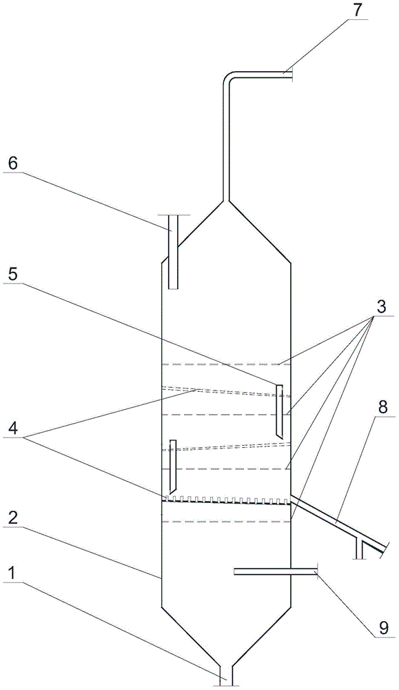
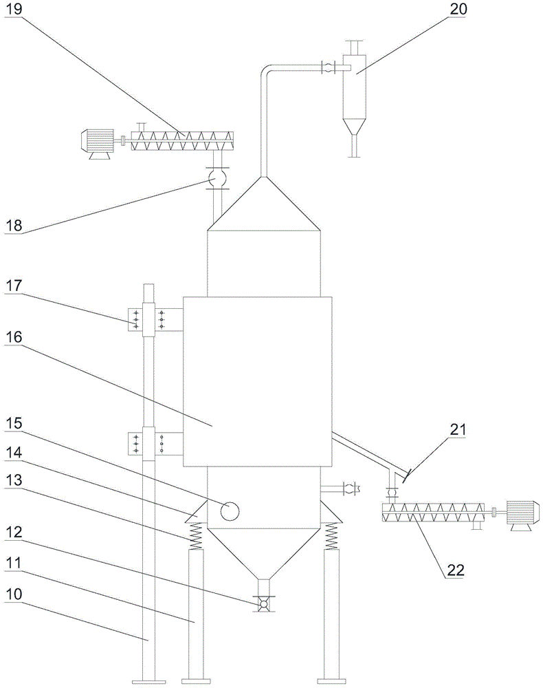
[0045] A vibrating fluidized bed reactor for continuous production of fluorinated rare earths according to the present invention, its main structure and connection mode are the same as those of the vibrating fluidized bed reactor described in the above specific embodiments, including the feeding device 19 , discharge device 22, fluidized bed, vibrator 15 and heating device; Fluidized bed comprises approximately cylindrical fluidized bed body 2, and the top of fluidized bed body 2 is a cone shape, and the bottom is an inverted cone Tubular shape, the middle body is cylindrical. The top of the fluidized bed body 2 is provided with a rare earth-containing material feed port 6 connected with the feed device 19; the middle and lower part of the fluidized bed body 2 is provided with a fluoride rare earth product discharge port 8 connected with the discharge device 22 . The bottom of the fluidized bed body 2 is also provided with a gas inlet 9 containing hydrogen fluoride. The cavit...

Embodiment 2

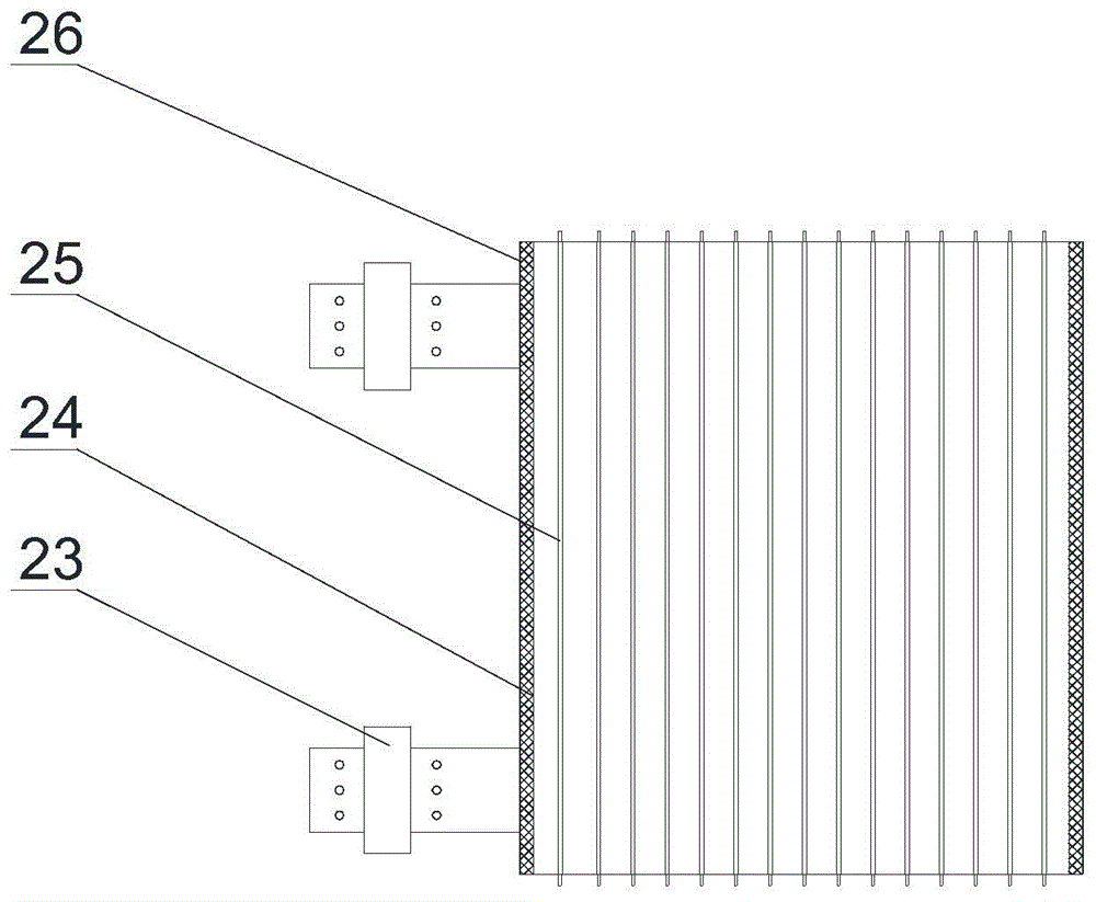
[0061] A vibrating fluidized bed reactor for continuous production of rare earth fluorides according to the present invention, its main structure and connection mode are the same as those of the vibrating fluidized bed reactor described in Example 1 above, the only difference is: The gas distribution plate 4 in this embodiment has four layers, and the opening ratio of each gas distribution plate is 1% to 6%.

[0062] The method for continuously producing cerium fluoride using the vibrating fluidized bed reactor of this embodiment may further comprise the steps:

[0063] (1) Start the heating device to heat the cavity of the uppermost gas distribution plate 4 set in the fluidized bed body 2 to 250°C;

[0064] (2) Evenly add rare earth-containing material cerium carbonate particles into the vibrating fluidized bed reactor through the feed device 19, and the cerium carbonate particles enter the cavity of the fluidized bed body 2 through the rare earth-containing material feed por...

Embodiment 3

[0070] A vibrating fluidized bed reactor for continuous production of rare earth fluorides according to the present invention, its main structure and connection mode are the same as those of the vibrating fluidized bed reactor described in Example 1 above, the only difference is: In this embodiment, the opening ratio of each gas distribution plate is 2.5% to 12.5%; the discharge port 8 of the rare earth fluoride product is externally connected to the discharge pipe, and the center line of the discharge pipe is 60 to the cylinder wall of the fluidized bed body 2. ° included angle, the vibrator is an air turbine vibrator.

[0071] The method for continuously producing neodymium fluoride using the vibrating fluidized bed reactor of this embodiment comprises the following steps:

[0072] (1) Start the heating device to heat the cavity of the uppermost gas distribution plate 4 set in the fluidized bed body 2 to 250°C;

[0073] (2) Evenly add rare earth-containing material neodymiu...


PUM

PropertyMeasurementUnit
porosityaaaaaaaaaa
porosityaaaaaaaaaa
porosityaaaaaaaaaa

Abstract

The invention discloses a vibratory fluidized bed reactor for continuous production of rare earth fluorides. The vibratory fluidized bed reactor comprises a feeding device, a discharging device, a fluidized bed, a vibrator and a heating device, wherein a rare-earth-containing material feeding hole is formed in the upper part of a fluidized bed body; a rare earth fluoride product discharge opening communicated with the discharging device is formed in the lower part of the fluidized bed body; a hydrogen-fluoride-containing gas inlet is formed in the bottom of the fluidized bed body; gas distribution plates through which hydrogen-fluoride-containing gas passes and uniform air distribution is realized are arranged in the cavity of the fluidized bed body; an exhaust pipe is arranged on the top of the fluidized bed body; the heating device is arranged on the outer side of the fluidized bed body and covers the fluidized bed body; the vibrator is arranged on the outer wall of the fluidized bed body; the bottom of the fluidized bed body is connected to supports through elastic supporting pieces. According to the scheme in the invention, the fluidization quality can be improved, the mass transfer and heat transfer effects are improved, the production efficiency is high, and the product is uniform and stable in quality, high in fluorination rate and low in process cost.

Description

technical field [0001] The invention relates to a fluidized bed reactor and its application, in particular to a vibrating fluidized bed reactor and a method for producing rare earth fluorides. Background technique [0002] Rare earth fluoride is an important raw material for the production of rare earth metals and alloys by molten electrolysis and calcithermal reduction. In addition, it is also used as an additive for steel and non-ferrous alloys, as an additive for rare earth polishing powder, and as a fluorescent powder. It has a wide range of uses. The production methods of rare earth fluoride mainly include wet method and dry method. Due to the long process of producing rare earth fluoride by wet method, heavy pollution, and high content of crystal water and impurities in the product, it has been gradually listed at home and abroad. Into the elimination process. Dry production has the advantages of simple process, less pollution, no crystal water, and low impurity conte...

Claims


Application Information

Patent Timeline
Patent Type & Authority Applications(China)
IPC IPC(8): B01J8/40C01F17/00
Inventor 丁喻唐三川宁顺明陈文勇何利民吴杰
Owner CHANGSHA RES INST OF MINING & METALLURGY
Why Eureka
Try Eureka