Robot cleaner system and method of controlling the same

a robot cleaner and robot technology, applied in the field of robot cleaner systems, can solve the problems of high cost, inconvenient cleaning, and inability to detect rf signals in a wide cleaning area or complex area, and achieve the effect of reducing the cost of manufacturing the robot cleaner system

Inactive Publication Date: 2008-01-03
SAMSUNG ELECTRONICS CO LTD
View PDF20 Cites 30 Cited by
  • Summary
  • Abstract
  • Description
  • Claims
  • Application Information

AI Technical Summary

Benefits of technology

[0008]The present invention has been made in view of the above-mentioned problems, and an aspect of the invention is to provide a robot cleaner system in which, instead of a vision system requiring expensive equipment such as a camera, a relative position between a robot cleaner and a station is determined by observing Doppler shift using relatively inexpensive devices so that costs of manufacturing the robot cleaner system are reduced, and a control method thereof.

Problems solved by technology

However, when using the detection of the RF signal, since the transmission distance of the RF signal is relatively shorter and the sensitivity of the RF signal is significantly reduced by the obstacle, the method of using the detection of the RF signal does not suit a wide cleaning area or an intricate area.
When the camera is used, since an expensive camera must be installed and software having a complicated algorithm for the analysis of the image is required, high costs are incurred.

Method used


Image

  • Robot cleaner system and method of controlling the same
  • Robot cleaner system and method of controlling the same
  • Robot cleaner system and method of controlling the same

Examples


first embodiment

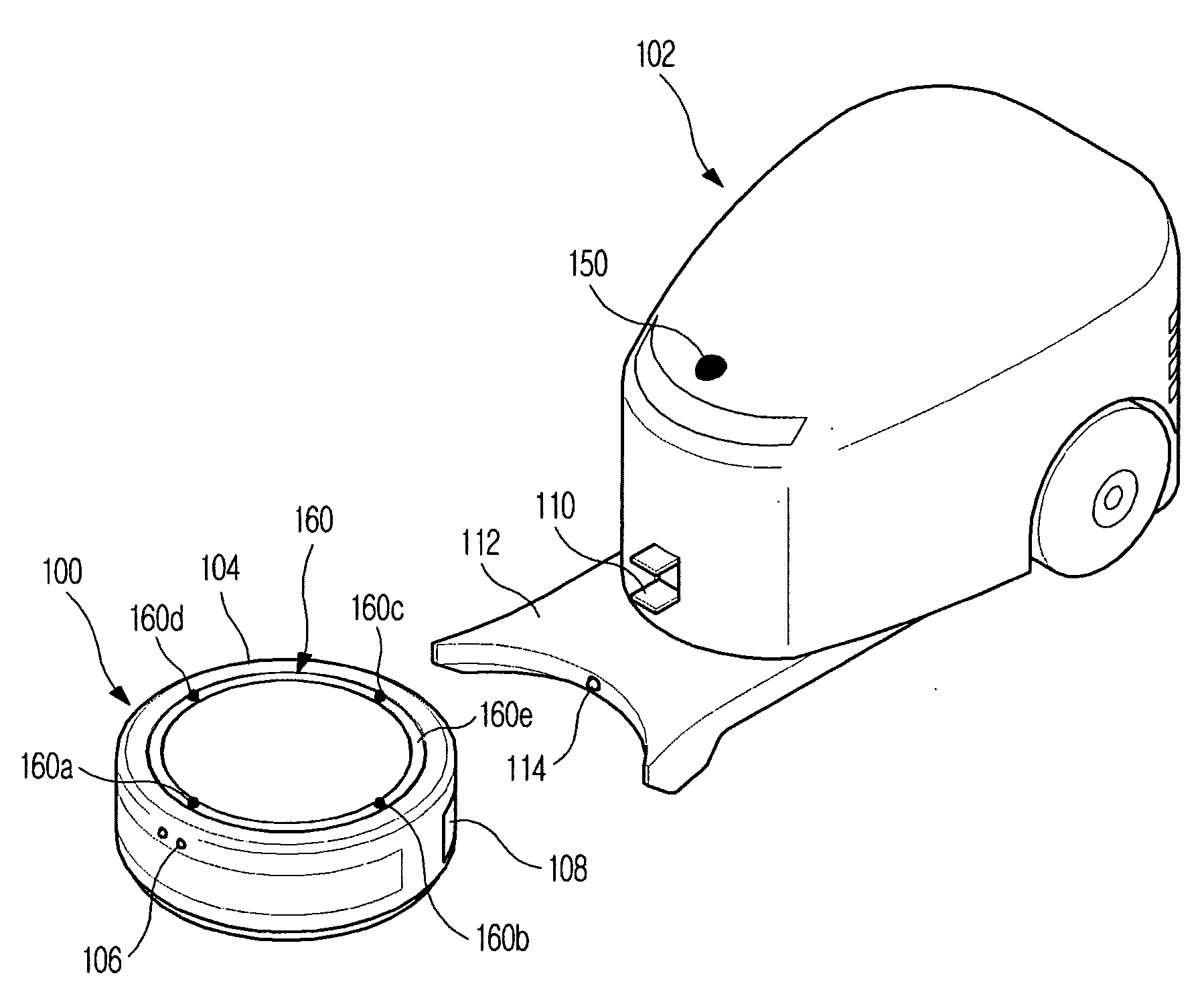
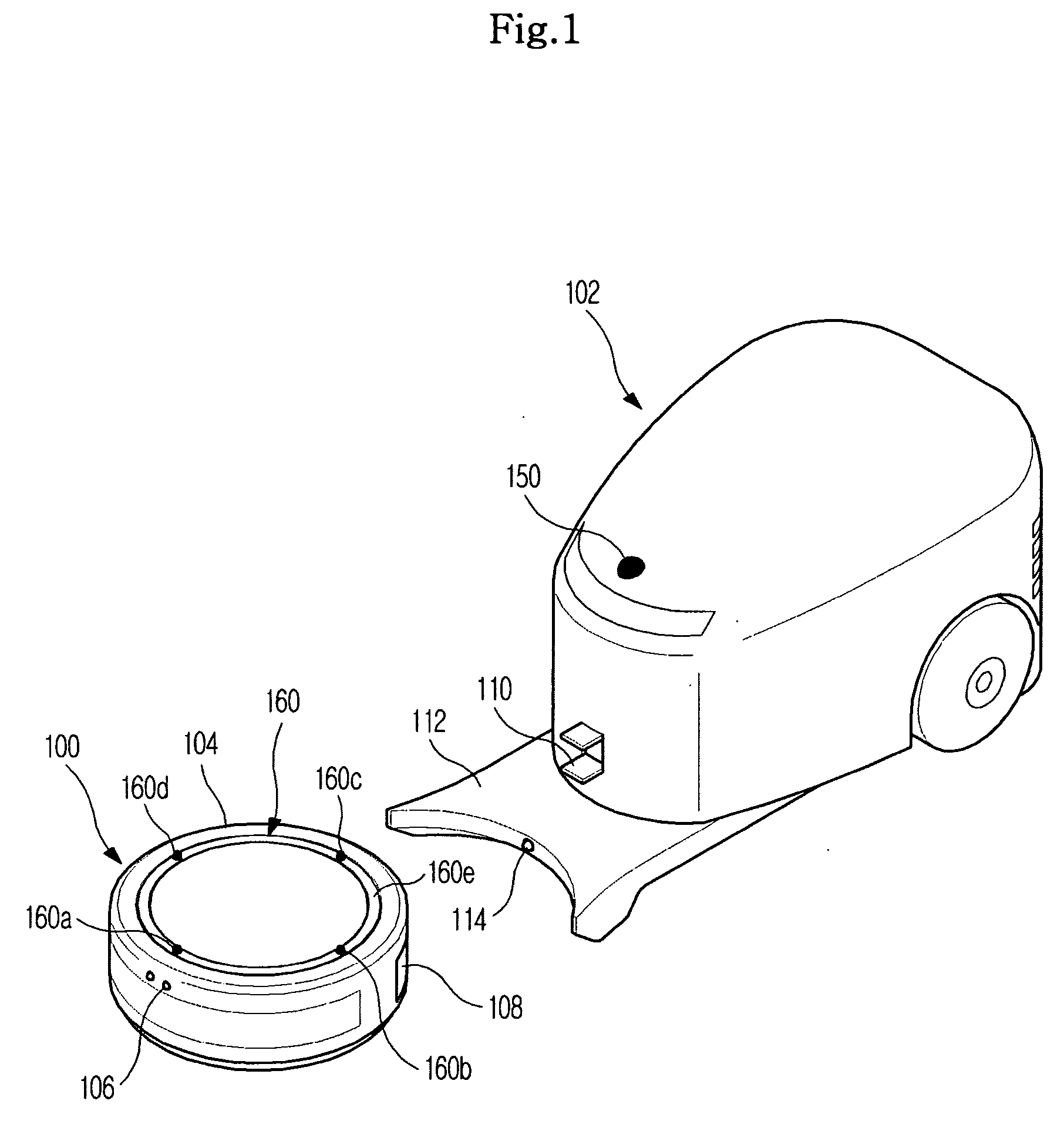
[0080]FIG. 1 is a perspective view illustrating a robot cleaner system according to the present invention. As shown in FIG. 1, the robot cleaner system includes a robot cleaner 100 and a docking station 102. The robot cleaner 100 travels an indoor space and suctions foreign substances on floor using a suctioning force caused by the rotation of a fan and / or static electricity caused by a charging device to clean the floor. The docking station 102 is provided to charge a battery of the robot cleaner 100 and to discharge the foreign substances therefrom.

[0081]In the lower side of a robot main body 104, electrically driven wheels (not shown) are installed to enable the robot cleaner 100 to travel. The wheels are driven by a driving motor (not shown) such that the robot cleaner 100 can perform a linear traveling and rotating. Moreover, in the outer side of the robot main body 104, an obstacle detecting sensor 106 such as an infrared sensor or an ultrasonic sensor are installed such that ...

second embodiment

[0107]FIG. 8 is a perspective view illustrating a robot cleaner system according to the present invention. As shown in FIG. 8, the robot cleaner system includes a robot cleaner 800 and a docking station 802. The robot cleaner 800 travels in an indoor space and suctions foreign substances on a floor using a suctioning force caused by the rotation of a fan and / or static electricity caused by a charging device to clean the floor, and the docking station 802 is provided to charge a battery of the robot cleaner 800 and to discharge the foreign substances therefrom.

[0108]In the lower side of a robot main body 804, electrically driven wheels (not shown) are installed to enable the robot cleaner 800 to travel. The wheels are driven by a driving motor (not shown) such that the robot cleaner 800 may perform a linear traveling and rotating. Moreover, in the outer side of the robot main body 804, an obstacle detecting sensor 806, such as an infrared sensor or an ultrasonic sensor, is installed ...

third embodiment

[0133]FIG. 13 is a view illustrating the detection of a position by observing the Doppler shift in the robot cleaner system according to the present invention. As shown in FIG. 13, three transmitters 150a to 150c are installed at predetermined points within an area 1300 where the robot cleaner 1200 works and the respective transmitters 150a to 150c transmit radio waves of natural frequencies different from each other. The robot cleaner 1200 receives the radio waves of the natural frequencies transmitted from the respective transmitters 150a to 150c by rotating the antennas 160a to 160d and observes the Doppler shift of the received radio waves so as to obtain the directions from the present position of the robot cleaner 120 with respect to the respective transmitters 150a to 150c, and detects angles θ4 and θ5 from the directions.

[0134]In other words, three points a1, a2, and a3 of the antenna (for example, 160a) of FIG. 13 are positions corresponding to the point a of FIG. 3 where t...


PUM


Abstract

A robot cleaner system and a control method thereof reduce manufacturing costs, expand a detected distance, and precisely control a movement and positioning of a robot cleaner. The robot cleaner system includes a robot cleaner and a station. One of the robot cleaner and the station transmits a signal of a predetermined frequency and the other receives the signal so that a direction toward the transmitting side for transmitting the signal is detected based on a Doppler shift observed by the receiving side that receives the signal.

Description

CROSS-REFERENCE TO RELATED APPLICATIONS[0001]This application claims the benefit of Korean Patent Application Nos. 2006-58980, 2006-58981 and 2006-58982, filed on Jun. 28, 2006, in the Korean Intellectual Property Office, the disclosure of which is incorporated herein by reference.BACKGROUND OF THE INVENTION[0002]1. Field of the Invention[0003]The present invention relates to a robot cleaner system and a method of controlling the same, and more particularly, to a method of controlling the movement and position of a robot cleaner system for freely traveling in a region to be cleaned and for automatically cleaning the region.[0004]2. Description of the Related Art[0005]A robot cleaner is an apparatus which spontaneously travels a predetermined sized cleaning area without user's manipulation and performs cleaning of dust, foreign substances, and the like on the floor. The robot cleaner determines a distance from an obstacle such as furniture, stationary objects, a wall, or the like, in...

Claims


Application Information

Patent Timeline
Patent Type & Authority Applications(United States)
IPC IPC(8): G05B19/00
CPCG05D1/0225G05D1/0242G05D2201/0203G05D1/0272G05D1/028G05D1/0255
Inventor CHUNG, WOO RAMJOO, JAE MANWEE, HOONKIM, DONG WONHONG, JUN PYOKIM, YONG TAE
Owner SAMSUNG ELECTRONICS CO LTD
Why Eureka
Try Eureka