Method for simulating a complex system with construction of at least one model including at least one modelled router, corresponding computer software package and storage means

a technology of complex systems and routers, applied in the field of complex systems, can solve the problems of insufficient functional modelling to decide upon production solutions, the inability to obtain architectural models capable of enabling analyses and evaluations, and the inability to model complex systems. , to achieve the effect of enabling analysis and evaluation, a new degree of complexity also appears with configurable and even dynamically reconfigurable products

Inactive Publication Date: 2008-01-03
INTEL CORP
View PDF5 Cites 3 Cited by
  • Summary
  • Abstract
  • Description
  • Claims
  • Application Information

AI Technical Summary

Benefits of technology

[0029] In other words, a new type of modelled functional component is used, named a modelled functional router, making it possible to route messages or transactions between modelled functional components (components) of the model. This makes it possible to facilitate the creation of functional models for complex systems.
[0039] In one advantageous example of the disclosure, said construction step makes it possible to obtain at least two simple models of the system each including at least one modelled router. Furthermore, said method includes constructing a more complex model of the system by combining said at least two simple models of the system, with the use of at least one modelled router to represent the required interconnections between said at least two simple models of the system.
[0043] In one particular example of the disclosure, the method includes distributed mapping of said functional model to said platform model, via distributed assignment of said at least one modelled functional router to said at least one modelled physical router, making it possible to obtain an architectural model of said complex system.

Problems solved by technology

The problem is then posed of creating models for these systems resulting from the association of a set of use cases, so as to produce scenarios representative of anticipated situations implementing several applications and services of the system.
Furthermore, functional modelling is not sufficient for deciding upon production solutions.
The architectural model capable of enabling analyses and evaluations thus becomes nearly impossible to obtain due to the complexity of the functional interconnections that are being produced via a distributed structure of physical interconnecting components.
A new degree of complexity also appears with configurable and even dynamically reconfigurable products.
Furthermore, the creation of an architectural model blending the behaviour of the application for a variety of use cases with the distributed topologies of the current or future platforms is a laborious and very time-consuming task.
Furthermore, any modification of the application or the platform requires redoing a large portion of the modelling work.
These difficulties seriously impede companies from investing in such developments of models, which means that the exploration of architectures does not occur and that, as a result, the performance levels of the architectural choices are only discovered very late in the development cycle, with a very significant risk of obtaining unsatisfactory malfunctions and constraints.
The major disadvantage of the aforesaid current technique is the significant amount of time and the high level of skill required for developing such models, due to the exponential growth in the work associated with the need to clearly express all potential communications.
A second resultant disadvantage is also the monolithic nature of the model.
A third disadvantage relates to the near impossibility of creating a complex multi-domain (and / or multi-application) model by integrating models, each developed for its domain.
The technique of re-using and integrating models considered to be IPs (Intellectual Properties) is not viable.
The above disadvantages lead to the situation wherein the designers do not explore possible architectures for such systems, due to reasons of cost and a lack of time, and therefore rely more upon their experience and even their intuition in making architecture choices.
This results in difficulties during the integration phase or even later during use of the product.
Furthermore, neither do companies fund knowledge and expertise per domain, due to the impossibility of ensuring multi-domain integration thereof.

Method used


Image

  • Method for simulating a complex system with construction of at least one model including at least one modelled router, corresponding computer software package and storage means
  • Method for simulating a complex system with construction of at least one model including at least one modelled router, corresponding computer software package and storage means
  • Method for simulating a complex system with construction of at least one model including at least one modelled router, corresponding computer software package and storage means

Examples


application example

2. Application Example

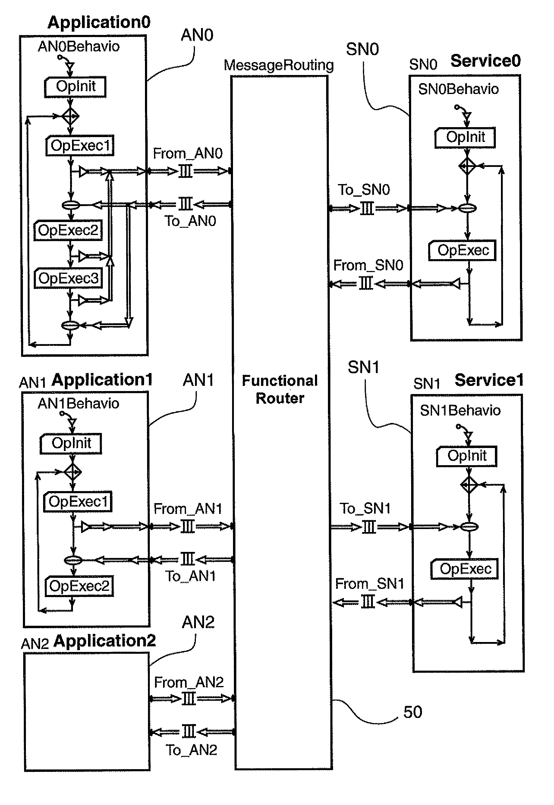
[0078] The modelled router technique of the disclosure applies in particular, but not exclusively, to the study of the architectures of complex electronic systems, whether it involves cards or systems integrated into a chip (SoC—System-on-Chip). These systems systematically integrate hardware and software as execution resources for services.

[0079] The study of such systems passes first through their functional and then architectural modelling. These models serve to provide checks and analyses of both functional and performance-related properties. The properties are obtained by simulation of the models. For more information, refer to the MCSE methodology (Design Method for Electronic Systems) and to the CoFluent Studio (registered trademark) tools of the CoFluent Design company (applicant of this patent application), which implement a portion of this MCSE methodology.

[0080] The modelled router technique of the disclosure most especially claims to be suited to ...


PUM


Abstract

A method is provided for constructing at least a functional model of a complex system including a plurality of components. The method includes constructing the functional model of the complex system, including a hierarchized set of modelled functional components. Each of the functional modelled components is an instance of an object class belonging to a specific set of object classes. The specific set of object classes includes a “Functional Router” class, representing an abstract model of a dummy router, which describes a set of interconnections between at least two modelled functional components, each instance of the “Functional Router” class being called a modelled functional router. The functional model of the system includes at least one functional modelled router.

Description

CROSS-REFERENCE TO RELATED APPLICATION [0001] None. FIELD OF THE DISCLOSURE [0002] The field of the disclosure is that of complex systems of the type including a plurality of components, e.g., such as one or more processors executing a set of functions under the control of a hierarchized set of schedulers. [0003] In this document, processor is understood to mean any execution resource unit. The disclosure is not limited only to the software and hardware processors used in electronic and computer systems, but also applies to mechanical processors (e.g., a robot which executes one or more tasks) or humans (e.g., an operator who executes one or more tasks). [0004] Furthermore, in this document, a scheduler is understood to mean a function capable of establishing an order of execution of functions or tasks for a processor used as a resource. This function can be carried out in software and / or hardware form, for the hardware or software processors, or by any other technique for the other...

Claims


Application Information

Patent Timeline
Patent Type & Authority Applications(United States)
IPC IPC(8): G06F17/50
CPCG06F17/5036G06F30/367
Inventor CALVEZ, JEAN-PAUL
Owner INTEL CORP
Why Eureka
Try Eureka