Hydraulic actuating device for actuating a shift rod in particular of a gearbox for motor vehicles

a technology of hydraulic actuation and shift rod, which is applied in the direction of belt/chain/gearing, engine without rotary main shaft, gear control, etc., can solve the problems of impairing the function of the actuating device and no air can collect, and achieves cost-effective manufacturing, small space, and simple and cost-effective manufacturing

Active Publication Date: 2008-01-10
FTE AUTOMOTIVE GMBH & CO KG
View PDF3 Cites 11 Cited by
  • Summary
  • Abstract
  • Description
  • Claims
  • Application Information

AI Technical Summary

Benefits of technology

[0007] As a result of this configuration of the actuating device, when at least one working chamber is acted upon by pressure medium any air located therein is entrained into the auxiliary chamber by the flow of pressure medium taking place across the sealing arrangement between said working chamber and the auxiliary chamber, from where the air can further pass with the pressure medium into the reservoir for the pressure medium. A deliberate (small) leakage thus takes place across the valve-like sealing arrangement from this working chamber which is acted upon by pressure medium to the auxiliary chamber provided for temporarily holding air, so that this working chamber which is acted upon by pressure medium can be vented in a conceivably simple manner. As a result, no air can collect in the working chambers of the actuating device, which could impair the function of the actuating device.
[0014] The cylinder chamber for accommodating the shift piston actively connected to the shift rod may in principle be formed by the gear housing itself, or by a cylinder housing which is flanged onto the gear housing. However, with regard to simple and cost-effective manufacture and a small space requirement, preference is given to an embodiment of the actuating device according to the invention in which the cylinder chamber is formed by an insert which is inserted in a stepped bore in the gear housing and is fixed in the latter by means of a cover attached to the gear housing. In this case, the insert may advantageously be essentially beaker-shaped, with a bottom which has a central opening for the passage of the shift rod and delimits an annular channel with a step of the stepped bore in the gear housing, which annular channel communicates with a control connection for the working chamber closest to the interior of the gear housing, wherein the bottom of the insert is provided with a plurality of holes distributed over the circumference, which holes connect the working chamber closest to the interior of the gear housing to the annular channel, which in a simple manner ensures a large connection cross section between the control connection and this working chamber and moreover provides an angularly non-directional installation of the insert in the stepped bore of the gear housing. Advantageously, the insert may also serve to guide a hollow piston shaft of the shift piston which surrounds the shift rod.
[0015] Finally, with regard to cost-effective manufacture without the need for post-machining, it is preferred if the insert and / or the shift piston is injection-molded from a plastic. With regard to good abrasion resistance, polyphthalamide (PPA) with a predetermined glass fiber content, for example PPA with a 50% glass fiber content, has proven to be advantageous as a material for the insert and / or the shift piston.

Problems solved by technology

As a result, no air can collect in the working chambers of the actuating device, which could impair the function of the actuating device.

Method used


Image

  • Hydraulic actuating device for actuating a shift rod in particular of a gearbox for motor vehicles
  • Hydraulic actuating device for actuating a shift rod in particular of a gearbox for motor vehicles
  • Hydraulic actuating device for actuating a shift rod in particular of a gearbox for motor vehicles

Examples


Embodiment Construction

OF EMBODIMENTS

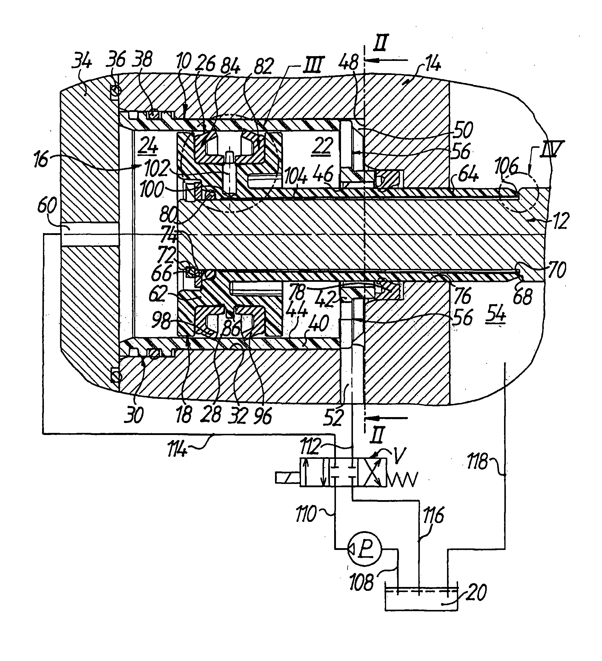
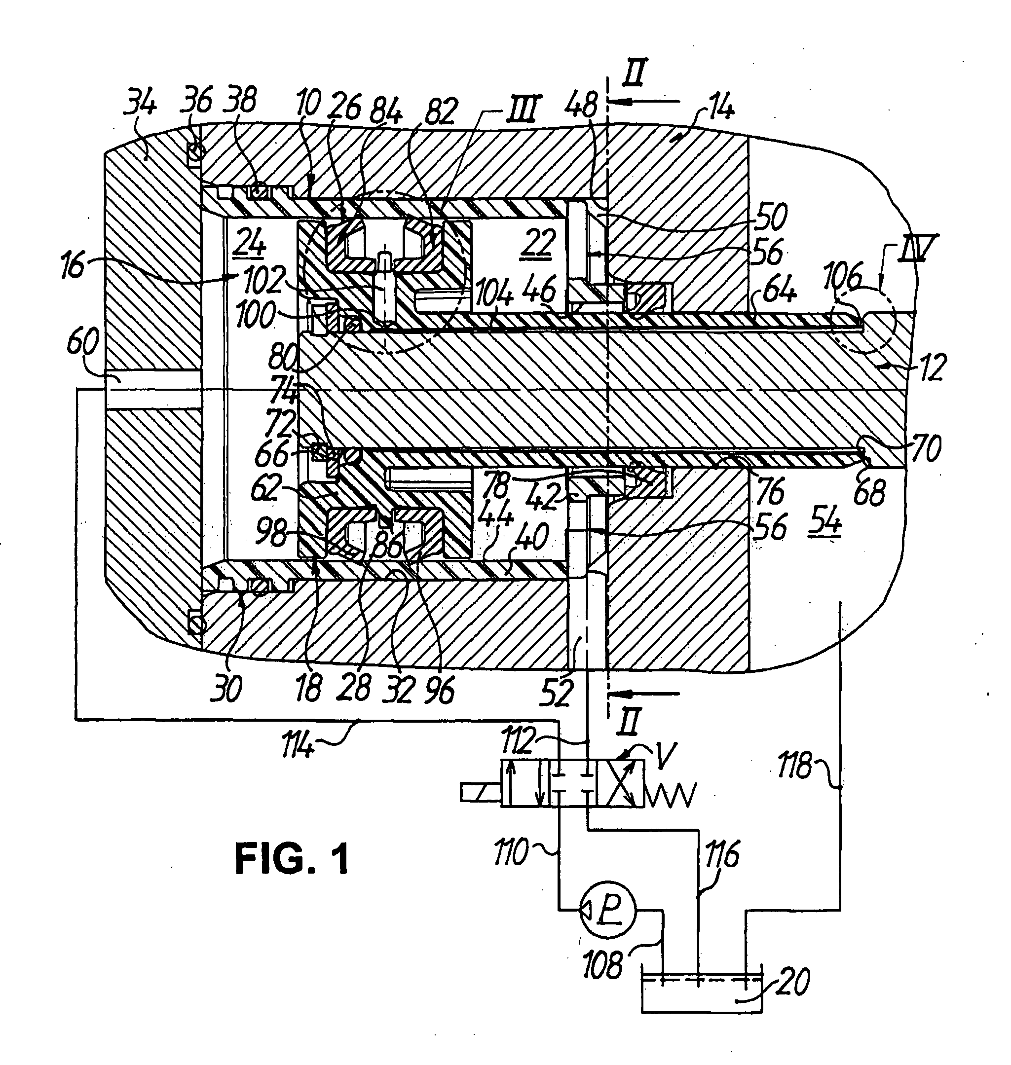
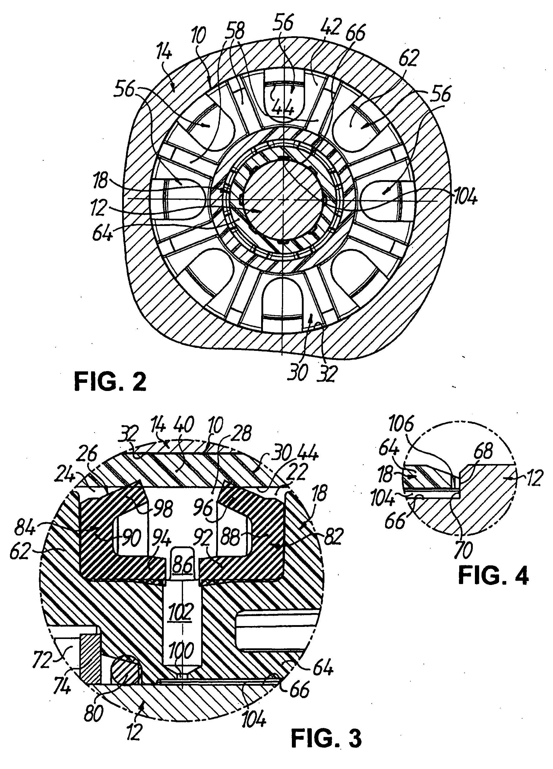
[0025]FIG. 1 shows a hydraulic actuating device 10 for actuating, i.e. axially displacing, a shift rod 12 in a gearbox for motor vehicles, the gear housing of which is denoted 14 in the figures. Provided in the gear housing 14 is a cylinder chamber 16 for accommodating a shift piston 18 actively connected to the shift rod 12. The shift piston 18 divides the cylinder chamber 16 into two working chambers 22, 24 which can selectively be acted upon by a pressure medium, in the present case a hydraulic oil, from a reservoir 20 (shown only schematically) for the pressure medium, which working chambers are separated from one another by means of a sealing arrangement 26 arranged on the shift piston 18. As will be explained in more detail below, it is essential that the sealing arrangement 26 is designed in a valve-like manner so that, when at least one working chamber 22, 24 is acted upon by pressure medium, it connects said working chamber to an auxiliary chamber 28 which is ...


PUM


Abstract

There is disclosed a hydraulic actuating device for actuating a shift rod in particular of a gearbox for motor vehicles, which comprises a cylinder chamber provided in or on a gear housing for accommodating a shift piston which is actively connected to the shift rod and which divides the cylinder chamber into two working chambers which can selectively be acted upon by a pressure medium from a reservoir for the latter, said working chambers being separated from one another by means of a sealing arrangement arranged on the shift piston. The sealing arrangement is designed in a valve-like manner so that, when at least one working chamber is acted upon by pressure medium, it connects said working chamber to an auxiliary chamber which is delimited by the sealing arrangement and which in turn can be connected to the reservoir for the pressure medium. As a result, a cost-effective hydraulic actuating device is provided which is vented in a simple and efficient manner during operation from the working chambers via the auxiliary chamber to the reservoir.

Description

TECHNICAL FIELD [0001] The invention relates to a hydraulic actuating device for actuating a shift rod. In particular, the invention relates to a hydraulic actuating device for actuating a shift rod of a gearbox for motor vehicles, as widely used in the motor vehicle industry for example for automatic gearboxes. Such an actuating device serves for example to actuate, i.e. to displace and optionally position, a shift fork attached to a shift rod of the gear mechanism in order to bring about a gear change. DESCRIPTION OF THE PRIOR ART [0002] For combined shifting of a mechanical gearbox in a vehicle, the generic document DE-A-195 43 646 discloses a pneumatic or hydraulic double-acting shift mechanism which comprises a shift cylinder flanged onto a housing of the gearbox. The shift cylinder has a working chamber or cylinder chamber for accommodating a shift piston, to which a piston rod or shift rod is attached by means of a screw connection. The shift piston divides the cylinder chamb...

Claims


Application Information

Patent Timeline
Patent Type & Authority Applications(United States)
IPC IPC(8): F16H63/30F15B15/17
CPCF15B15/149F15B15/204F16H61/30Y10T74/20024F16J15/48F16J15/56F15B15/1452F16H63/3023
Inventor REUL, ALEXANDERSTOSSEL, ROLANDMACHT, EGID
Owner FTE AUTOMOTIVE GMBH & CO KG
Why Eureka
Try Eureka