Sound attenuating sleeve for use on a piling

a sound attenuation and sleeve technology, applied in the direction of instruments, foundation engineering, construction, etc., can solve the problems of reducing the efficacy of the system, affecting the safety of marine life, and requiring time-consuming set-up, so as to reduce the cost of manufacturing, reduce the risk of injury or death, and reduce the effect of sound and/or shock waves

Inactive Publication Date: 2008-01-10
GUNDERBOOM
View PDF4 Cites 21 Cited by
  • Summary
  • Abstract
  • Description
  • Claims
  • Application Information

AI Technical Summary

Benefits of technology

[0014] The sleeve, by virtue of its size and design, is simpler to install and less expensive to manufacture than whole boom systems described in the prior art. Moreover, the sleeve can be designed to have both the traditional bubble curtain (emitted from diffusers, if present) as well as an arrangement of the inflated hoses that substantially surround a pile. The presence of hollow structures retained between the fabric materials that form much of the sleeve structure is particularly effective at attenuating harmful sound and / or shock waves. These combinations can be designed to reduce different harmful frequencies of sound and / or shock waves produced during the pile driving operation.

Problems solved by technology

As a result, underwater explosions or construction or demolition work quite often lead to severe injury or death of large numbers of marine life as a result of the crushing effect the sound or shock waves have on internal air cavities of the marine life.
One problem with this approach is that the air curtain is often dispersed by water flow such as from tidal currents, thereby decreasing its efficacy.
While these systems have proven effective in attenuating sound or shock waves, due to their size the systems require time consuming set up and significant expense in materials and fabrication.

Method used


Image

  • Sound attenuating sleeve for use on a piling
  • Sound attenuating sleeve for use on a piling
  • Sound attenuating sleeve for use on a piling

Examples


example 1

Testing of Hollow Plastic Spheres for Use in Sound Attenuation Sleeve

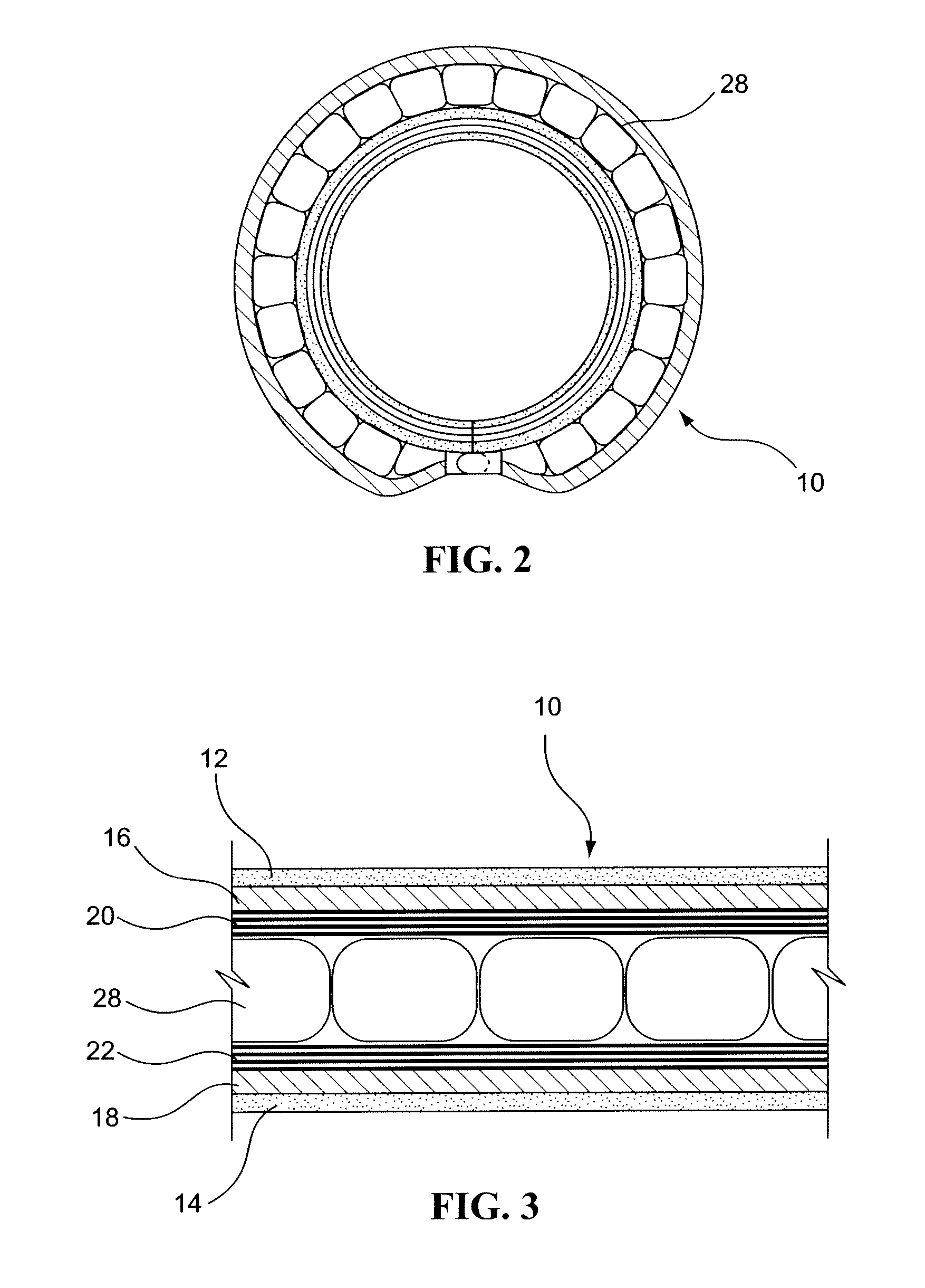
[0062] Hollow plastic spheres with diameters of approximately 1.5 inches (˜38.1 mm), 2.75 inches (˜69.9 mm), and 4.5 inches (˜114.3 mm) were selected for use in the sound attenuation sleeve based on the following data and analysis of the plastic spheres' ability to withstand pressure or collapse strength. These plastic spheres were as provided by McMaster-Carr and Product Components Corp.

[0063] To initially select which spheres were to be tested for collapse strength, the optimal diameter to attenuate sound at specific frequencies was estimated and their ability to reflect sound from the surface of the hollow plastic spheres. Maximum sound attenuation will occur when the interfering medium has a dimension approximately equal to multiples of ½ the wavelength of the sound generated. At dimensions of ¼ wavelengths of the sound, amplification can occur. This is analogous to the air gap to nullify the sound.

[0064] To...

example 2

Construction and Testing of Sound Attenuation Sleeve for Attenuation of 10 kHz Frequency

[0068] Based on the test results in Example 1, hollow plastic spheres with diameters of 1.5 inches (˜38.1 mm), 3 inches (˜76.2 mm), and 6 inches (˜152 mm) (all from McMaster-Carr) were selected for use in the sound attenuation sleeve. The sizes used in the fabricated sound attenuation sleeve were slightly different from those tested in Example 1, primarily because of availability and a desire to attenuate lower frequencies as shown in Table 1.

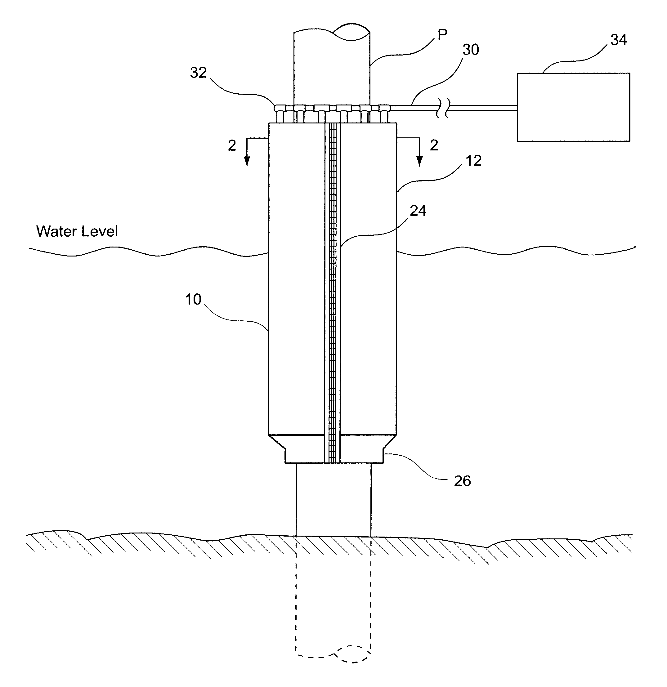
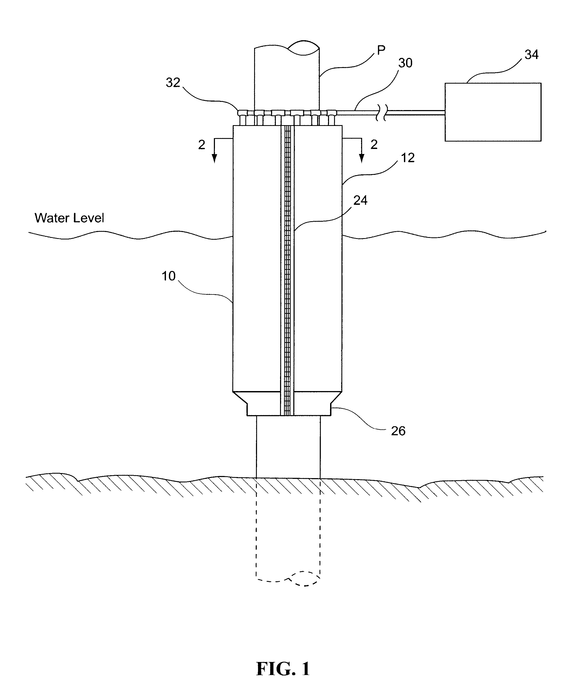
[0069] The sound attenuation sleeve was constructed according to the embodiment illustrated in FIGS. 5-8.

[0070] A simulation of high frequency sound generation was performed to assess the ability of the sound attenuation sleeve to attenuate transmission at 10 kHz. Testing was performed at the Chase Ocean Engineering Lab at the University of New Hampshire using their large tank (12.2 m×18.3 m×6 m depth). This tank afforded the spatial characteristics requi...


PUM


Abstract

Disclosed are a sound attenuation sleeve for use on a piling during underwater construction and a method of using such a sleeve for attenuating underwater transmission of sound and/or shock waves during underwater pile driving operations.

Description

[0001] This application claims the priority benefit of provisional U.S. Patent Application Ser. No. 60 / 805,542, filed Jun. 22, 2006, which is hereby incorporated by reference in its entirety.FIELD OF THE INVENTION [0002] The present invention relates to a sound attenuation sleeve for use on a piling during underwater construction and a method of using such for attenuating underwater transmission of sound and / or shock waves during underwater pile driving operations. BACKGROUND OF THE INVENTION [0003] Underwater explosives as well as construction and demolition work, in general, produce sound or shock waves that travel in all directions from the site of activity at a rate of approximately four times the speed it would travel in air. Water is also non-compressible, whereas air is compressible. Thus, water more effectively transmits the energy of the sound or shock wave to the surrounding environments. As a result, underwater explosions or construction or demolition work quite often lea...

Claims


Application Information

Patent Timeline
Patent Type & Authority Applications(United States)
IPC IPC(8): G10K11/00
CPCE02D13/005F16L55/0336
Inventor DREYER, HAROLD B.
Owner GUNDERBOOM
Why Eureka
Try Eureka