

Turntable and display apparatus
- Summary
- Abstract
- Description
- Claims
- Application Information
AI Technical Summary
Benefits of technology
Problems solved by technology
Method used
Image

Examples
embodiment 1
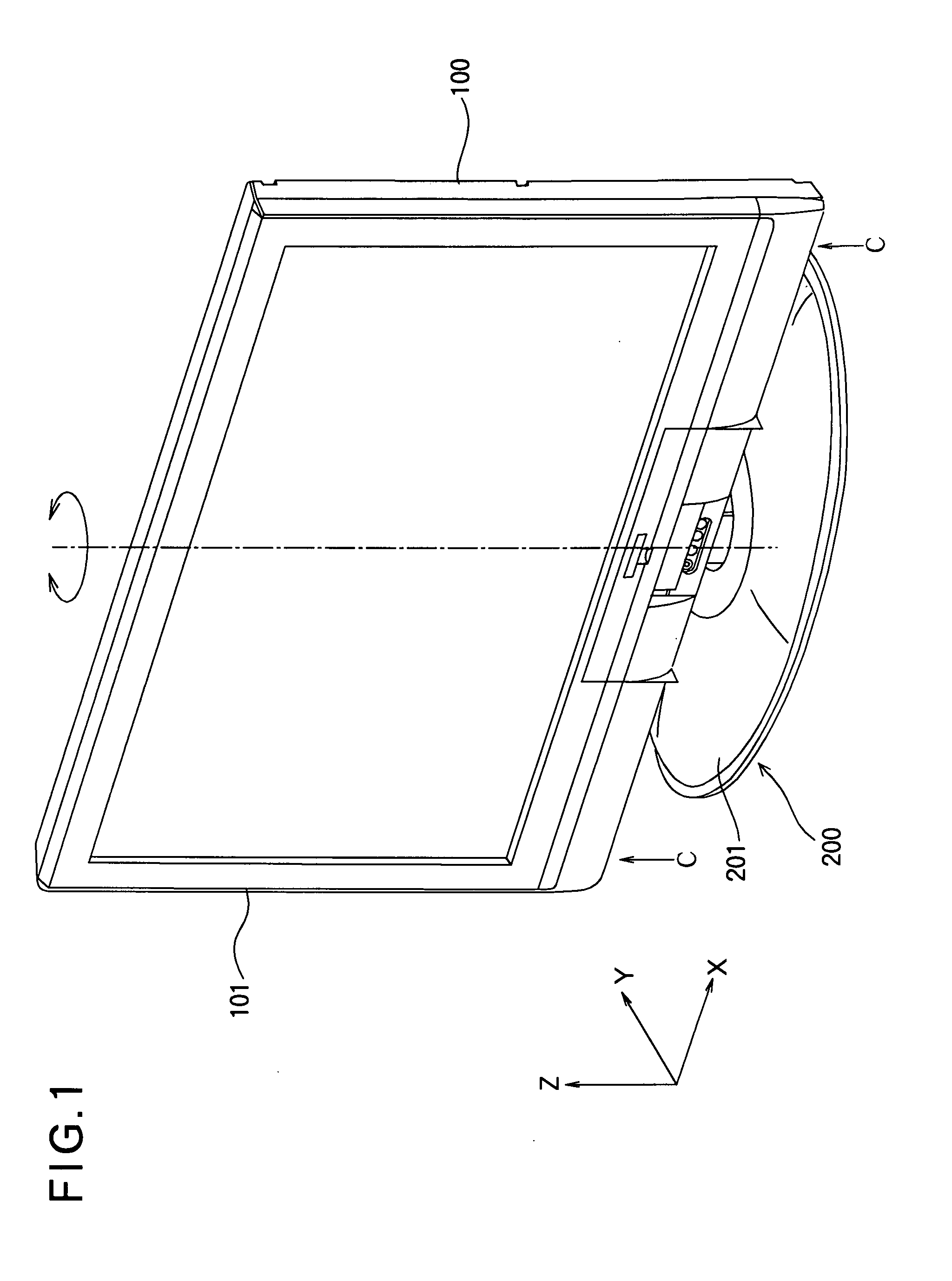
[0028]FIG. 1 is a perspective view showing the external shape of a display apparatus according to Embodiment 1 of the present invention. The display apparatus includes a display portion 100 having a display screen 101 for displaying an image or the like, and a turntable 200 on which the display portion 100 is mounted. The display portion 100 is, for example, an LCD television. The turntable 200 supports the display portion 100 so that the display portion 100 is rotatable about a vertical rotation axis (as an axis line) defined as Z-axis. By rotating the display portion 100, the display screen 101 can be oriented toward a user (viewer). The rotation axis is defined at, for example, a center position of the display screen 101 in the horizontal direction. A plane perpendicular to the Z-axis is defined as XY-plane.
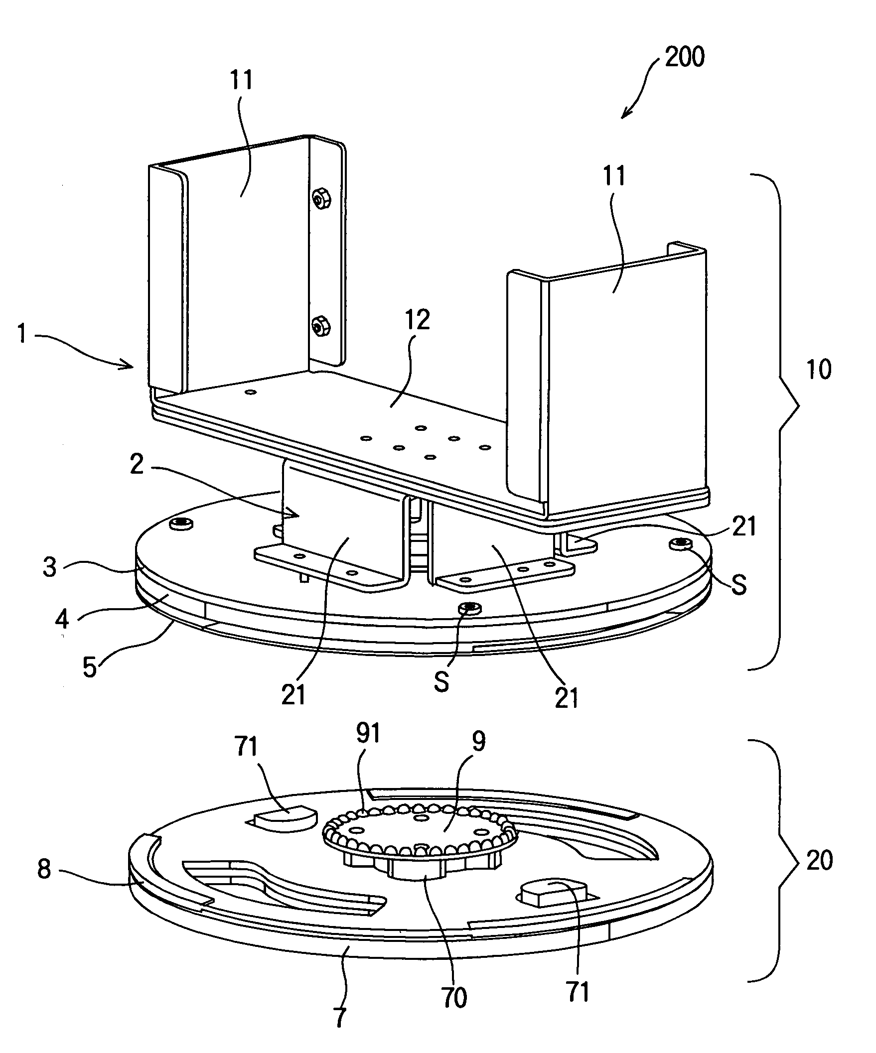
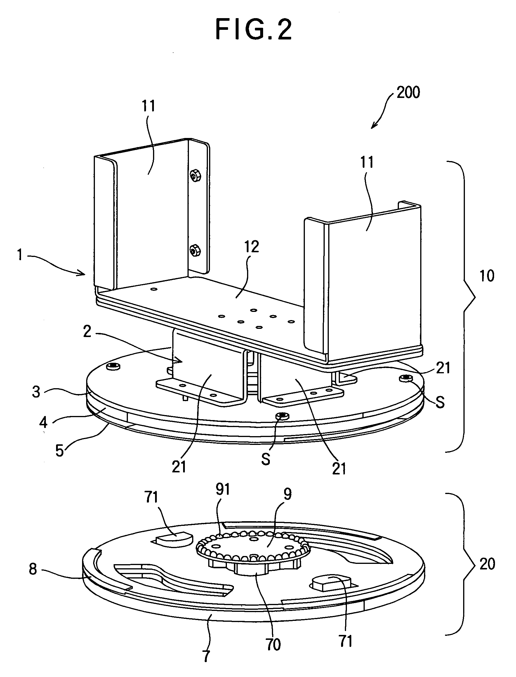
[0029]FIG. 2 is a perspective view showing the internal configuration of the turntable 200 in such a manner that the turntable 200 is divided into a rotatable unit and a fixed...
embodiment 2
[0057]In the above described Embodiment 1, the turntable 200 has one first friction plate 5 and one second friction plate 8. However, it is also possible to provide a plurality of the first friction plates and a plurality of the second friction plates. By changing the number of the first and second friction plates, the friction force (the rotational resistance) can be adjusted.
[0058]FIG. 9 is a schematic view showing a configuration example having another pair of a first friction plate 15 and a second friction plate 18, in addition to the first friction plate 5 and the second friction plate 8. In FIG. 9, components that are the same as those having been described in Embodiment 1 are assigned the same reference numerals.
[0059]In the configuration example shown in FIG. 9, the first friction plate 15, the second friction plate 18, the first friction plate 5, the second friction plate 8 are disposed between the fixed plate 7 and the rotatable plate 4 in this order from the fixed plate 7...
embodiment 3
[0062]In the above described Embodiment 1, the concaves 91 are formed on the retaining plate 9, and the protrusions 31 (engaging the concaves 91) are formed on the rotatable base 3. However, it is possible to provide the concaves on the rotatable base 3 and to provide the protrusions on the retaining plate 9.
[0063]FIG. 10 shows a configuration example where concaves 35 are provided on the rotatable base 3 and where protrusions 95 (engaging the concaves 35) are formed on the retaining plate 9. In FIG. 10, components that are the same as those having been described in Embodiment 1 are assigned the same reference numerals.
[0064]In the configuration example of FIG. 10, the concaves 35 of the rotatable base 3 and the protrusions 95 of the retaining plate 9 are able to engage each other at predetermined rotational positions. The other configuration is the same as Embodiment 1. In the configuration example of FIG. 10, even if the turntable 200 is going to rotate relative to the display por...
PUM
 Abstract
Description
Claims
Application Information