Optical generic switch panel

a switch panel and generic technology, applied in the direction of electrical equipment, instruments, electric digital data processing, etc., can solve the problems of difficult reconfiguration of mechanical switch panels, increased cost and product cycle time of devices that utilize such panels, and significantly more expensive touch screens than conventional switches

Inactive Publication Date: 2008-01-10
AVAGO TECH GENERAL IP SINGPAORE PTE LTD
View PDF13 Cites 53 Cited by
  • Summary
  • Abstract
  • Description
  • Claims
  • Application Information

AI Technical Summary

Problems solved by technology

Mechanical switch panels are difficult to reconfigure, and hence, tend to be customized for each application.
This substantially increases the cost and product cycle time of devices that utilize such panels.
Touch screens, however, are significantly more expensive than conventional switches, and hence, are not always feasible for many applications.
In addition, the ambient light intensity can interfere with the display that prevents the user from seeing the simulated buttons.
Furthermore, the device cannot distinguish between an accidental light touch and an intended button push, since the screens do not provide a measure of the pressure with which the user has pressed his or her finger on the screen.
Since the observed changes depend on the shape of the screen, custom screen sizes are limited and can require special programming.
Second, the system requires an imaging system that views the touch screen.
Imaging systems require optics and a significant amount of space.
This increases the thickness of the display.
In addition, the various optical components must be mounted and aligned, which increases the cost of the display.
Finally, non-planar switch panels impose serious limitations on the optics, since the non-planar surface must be imaged onto the imaging array.

Method used


Image

  • Optical generic switch panel
  • Optical generic switch panel
  • Optical generic switch panel

Examples


Embodiment Construction

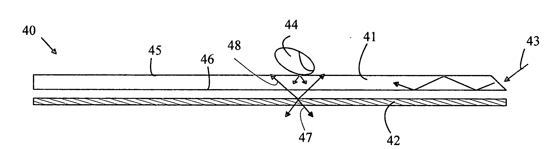
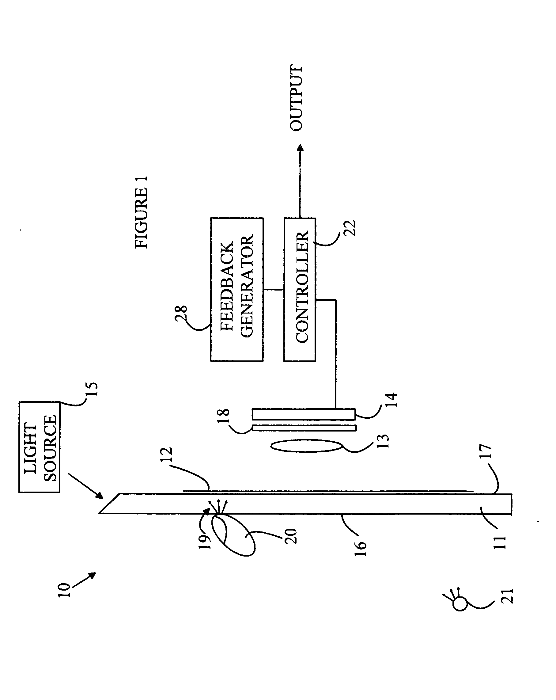
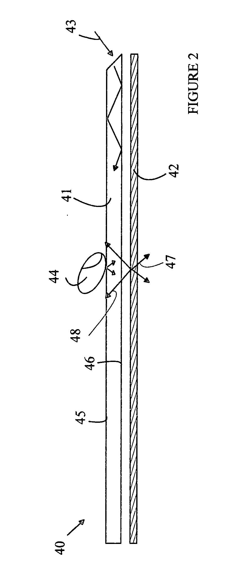
[0013]The manner in which the present invention provides its advantages can be more easily understood with reference to FIG. 1, which is a cross-sectional view of a switch panel 10 according to one embodiment of the invention described in the co-pending patent applications discussed above. Switch panel 10 utilizes a transparent screen 11 that emits light at the point of contact when a user presses the user's finger 20 against the screen.

[0014]Surface 16 is imaged onto a photodetector array 14 by lens 13. Photodetector array 14 can be constructed from a CCD camera array of the type used in optical mice, inexpensive cameras, or the like. The output of the photodetector array is processed by a controller 22 that generates an output signal indicative of the “button” pushed by the user.

[0015]The output “signal” generated by controller 22 can take a number of forms. For example, controller 22 can generate an electrical signal. In addition, controller 22 can include switches and / or relays ...


PUM


Abstract

A switch panel having a touch plate, light converter, and light analyzer are disclosed. The touch plate includes an optically transparent layer having first and second surfaces, and having an index of refraction greater than that of air. The touch plate conducts light of an excitation wavelength between the first and second surfaces and emits part of that light through the second surface at one of a plurality of emission locations depending on the position at which pressure is applied to the first surface. The light converter is positioned to receive the light emitted through the second surface and generates light having a plurality of distinct location-specific spectra, one of the location-specific spectra corresponding to each of the emission locations. The light analyzer generates a signal indicative of which of the location-specific spectra was generated by the light converter.

Description

BACKGROUND OF THE INVENTION[0001]Control systems for various apparatuses rely on a plurality of switches to input data to the apparatus. Switch arrays based on mechanical switches mounted on a surface are well known in this regard. Simulated switch arrays that utilize touch screens are also well known. Mechanical switch panels are difficult to reconfigure, and hence, tend to be customized for each application. This substantially increases the cost and product cycle time of devices that utilize such panels.[0002]Input devices based on touch screens provide a convenient method for inputting commands in a manner that is easily reconfigurable. In such devices, the button pattern is displayed on the screen and the user selects a “button” by touching the screen over the button image. Touch screens, however, are significantly more expensive than conventional switches, and hence, are not always feasible for many applications. In addition, the ambient light intensity can interfere with the d...

Claims


Application Information

Patent Timeline
Patent Type & Authority Applications(United States)
IPC IPC(8): G06M7/00
CPCG06F2203/04109G06F3/0421
Inventor OON, CHIN HINKEH, KEAN LOOCHEN, FARN HINWARD, CALVIN B.
Owner AVAGO TECH GENERAL IP SINGPAORE PTE LTD
Why Eureka
Try Eureka