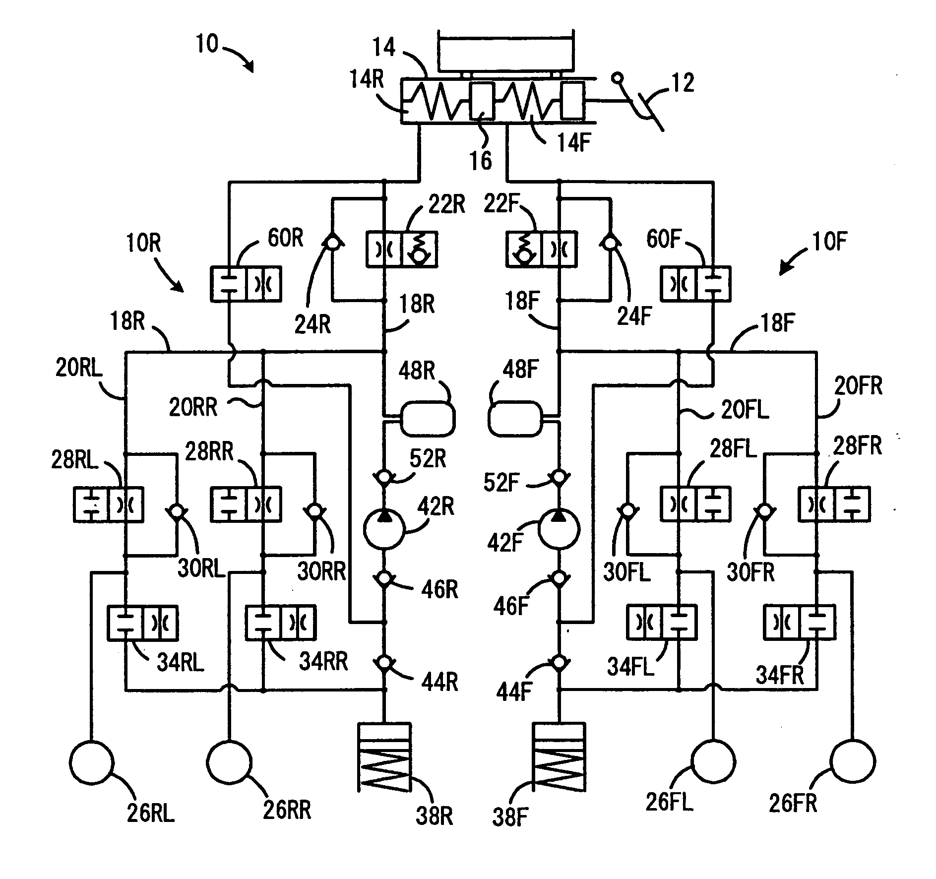
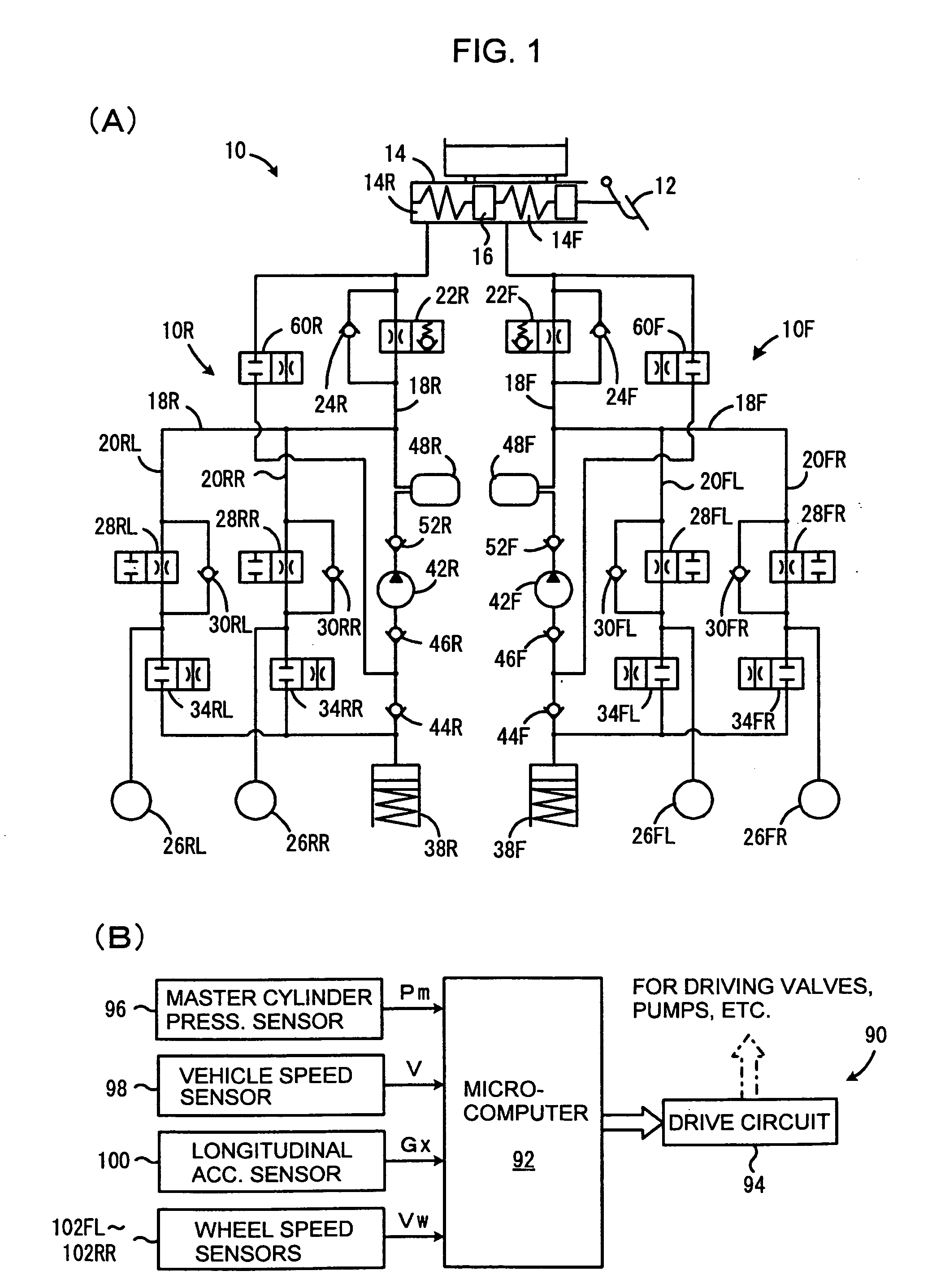
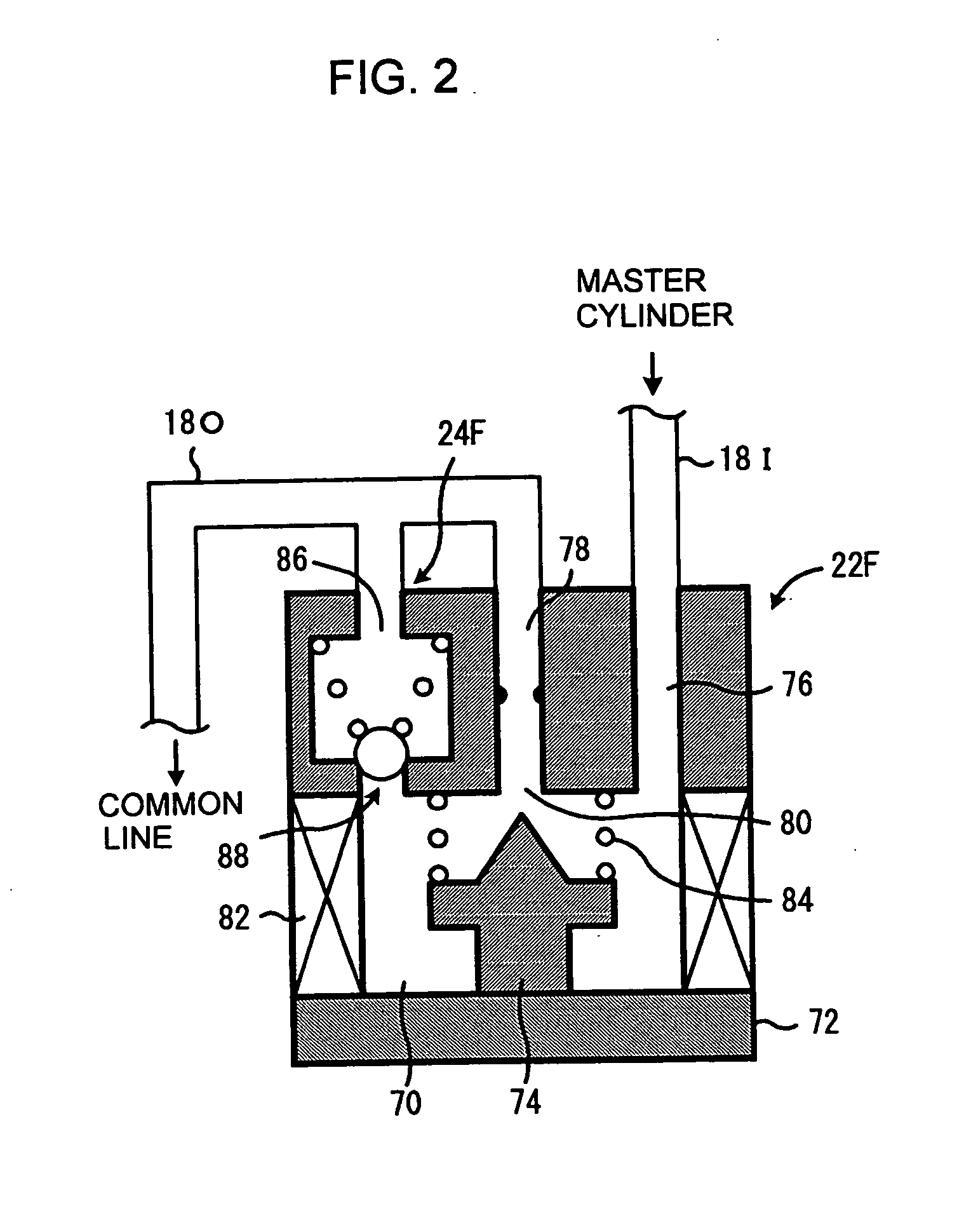
Braking force control system for vehicles

Inactive Publication Date: 2008-01-10
TOYOTA JIDOSHA KK
View PDF4 Cites 26 Cited by
  • Summary
  • Abstract
  • Description
  • Claims
  • Application Information

AI Technical Summary

Benefits of technology

[0007] According to the present invention, there is provided such a braking force control system for a fluid or oil hydraulic brake system of a vehicle in which, when a braking force increasing control for increasing the braking force as compared with that corresponding to the braking operation by the driver when the driver makes a quick braking operation and a braking force increase suppressing control for suppressing the increase of the braking force of a selected wheel

Problems solved by technology

(A larger pressure difference across the control valve is apt to cause an excessive braking pressure.)
However, if the increase of the braking root pressure in the upstream of the control valve of the wheel at which the braking force increase suppressing control is executed is completely prohibited in the way of the braking fo

Method used


Image

  • Braking force control system for vehicles
  • Braking force control system for vehicles
  • Braking force control system for vehicles

Examples


Example

First Embodiment

[0062]FIG. 4 is a flowchart showing a first embodiment of the process for calculating the target pressure increases Pcft and Pcrt in step 100 of FIG. 3. In brief, the calculation process of FIG. 4 is constructed to prohibit the pressure increase of the braking root pressure of each of the front and rear wheels when the braking pressure increase suppressing control has been started for all of the wheel cylinders of each of the front and rear wheels or the probability thereof is high.

[0063] In the calculation process of FIG. 4, first it is judged if the braking pressure increase suppressing control has been started for all of the wheel cylinders belonging to the front root passage or the probability thereof is high. More concretely, it is judged (a) if the anti-skid control has been started for the front left and front right wheels (step 110), (b) if the anti-skid control has been started for one of the front left and front right wheels, while the braking pressure in...

Example

Second Embodiment

[0080]FIG. 7 is a flowchart showing the flow of control in the second embodiment of the calculation process of the target pressure increases Pcft, Pcrt in step 100 of the flowchart of FIG. 3. In brief, the calculation process of FIG. 7 is constructed such that when it is judged that the braking force increase suppressing control was started for all of the wheel cylinders connected to each of the circuits for the front and rear wheels or the probability thereof is high, the increasing gradient of the braking root pressure increase is decreased as compared with when it is not judged that braking force increase suppressing control was started or the probability thereof is high. This control is different from that shown in FIG. 4 in that, when it was judged that the braking pressure increase suppressing control was started for all of the wheel cylinders connected to each of the circuits for the front and rear wheels or the probability thereof is high, i.e. when any of ...

Example

Third Embodiment

[0087] With regard to the calculation process of the target pressure increase Pcft, Pcrt in step 100 of the flowchart of FIG. 3, a third embodiment may be executed in the same manner as the second embodiment shown in the flowchart of FIG. 7. The difference from the second embodiment is in that in the determination of the target increase amount ΔPcft, ΔPcrt or ΔPcft1, ΔPcrt1 in steps 240 and 290 of FIG. 7, the target increase amounts are each converged to zero as shown in FIG. 9. In other words, the final target amounts become the amounts integrating ΔPcft, ΔPcrt or ΔPcft1, ΔPcrt1 of the graph of FIG. 9. Therefore, the pressure increase of the braking root pressure during the brake assist control increases toward the final target amount which is the integration of the map of FIG. 9.

[0088] Referring to FIG. 9, with respect to the target increase amount of the front wheels, for example, ΔPcft1 given in step 240 is set to be an amount which is smaller than ΔPcft given ...


PUM


Abstract

According to the braking force control system of the present invention it is prevented that the the braking root pressure is increased unnecessarily high when the braking force increase suppressing control was initiated during the execution of the brake assist control without losing the effects of increasing the braking force available when the brake assist control only is executed. When the brake assist control is initiated, the pressure increase Pcf, Pcr of the braking root pressure of the front and rear wheels is increased relative to the master cylinder pressure Pm, but when the anti-skid control is executed for the left and right of the front or rear wheels, when the anti-skid control is executed for one of the front left and right wheels, while a yaw behavior control is executed for the other of the front left and right wheels, or when a braking force front/rear distribution control is executed, during the execution of the anti-skid control, the increase of the braking root pressure for the front or rear wheels is suppressed.

Description

FIELD OF THE INVENTION [0001] The present invention relates to a braking force control system for vehicles, and more particularly, to an electronic braking force control system for vehicles. BACKGROUND OF THE INVENTION [0002] It is known to execute a brake assist control so as to generate a higher braking force than usual by a normal braking action when the driver depresses the brake pedal quickly when a vehicle such as an automobile is running. In a vehicle equipped with a common fluid (oil) hydraulic brake system, the brake assist control is executed such that the master cylinder pressure varying according to the depression of the brake pedal by the driver is increased by a pump before being supplied to the wheel cylinders of the respective wheels, or an oil pressure generated by a pump separately from the master cylinder is supplied to the wheel cylinders of the respective wheels, so that thereby a strong braking force is generated corresponding to an increased oil pressure in th...

Claims


Application Information

Patent Timeline
IPC IPC(8): B60T8/171G06F17/00
CPCB60T8/1755B60T8/17616B60T2201/03B60T8/3275B60T8/1766
Inventor MIZUTANI, YASUJI
Owner TOYOTA JIDOSHA KK
Why Eureka
Try Eureka