Electromagnetic surveying

a technology of electromagnetic surveying and pore fluid, applied in the field of electromagnetic surveying, can solve the problems of transmission loss, difficulty in transmitting a high-power electric signal along a cable then, and inability to distinguish between the different possible compositions of pore fluids inside,

Inactive Publication Date: 2008-01-10
MILNE JAMES +3
View PDF20 Cites 35 Cited by
  • Summary
  • Abstract
  • Description
  • Claims
  • Application Information

AI Technical Summary

Benefits of technology

[0015] The control module may be located in a surface vehicle and used remotely to control the EM field generated by the submersible electromagnetic field generator. This in turn enables the generation of subsea EM fields having known and / or variable profiles and allows the generation of the EM fields to be synchronized with the surface-located control module.

Problems solved by technology

Whilst seismic surveying is able to identify such structures, the technique is often unable to distinguish between the different possible compositions of pore fluids within them, especially for pore fluids which have similar mechanical properties.
The normal difficulties of transmitting a high power electric signal along a cable then apply, such as transmission loss, timing drift, impedance matching and so forth.
However, although the seawater provides a path for current flow between the electrodes, it also provides a load with an inherently high inductance.
In practice, this has proved problematic, since the high inductance of the load causes the generation of a back EMF when the current is switched.
The effect of the back EMF is to produce voltage transients that can be damaging to components within the waveform driving signal source.
Through extensive and successful use, the limitations of the known cyclo-converter design have become apparent.
Variations in phase and amplitude of the AC signal generated by the antenna are undesirable.
These problems arise in large part due to drift and variable attenuation during the transmission of the AC signal from topside to ROV.
For example, degradation of the AC signal can produce erroneous zero-crossing points or cause non-detection of a real zero-crossing point, which may in turn result in a polarity switching event being triggered at an incorrect instant.

Method used


Image

  • Electromagnetic surveying
  • Electromagnetic surveying
  • Electromagnetic surveying

Examples


Embodiment Construction

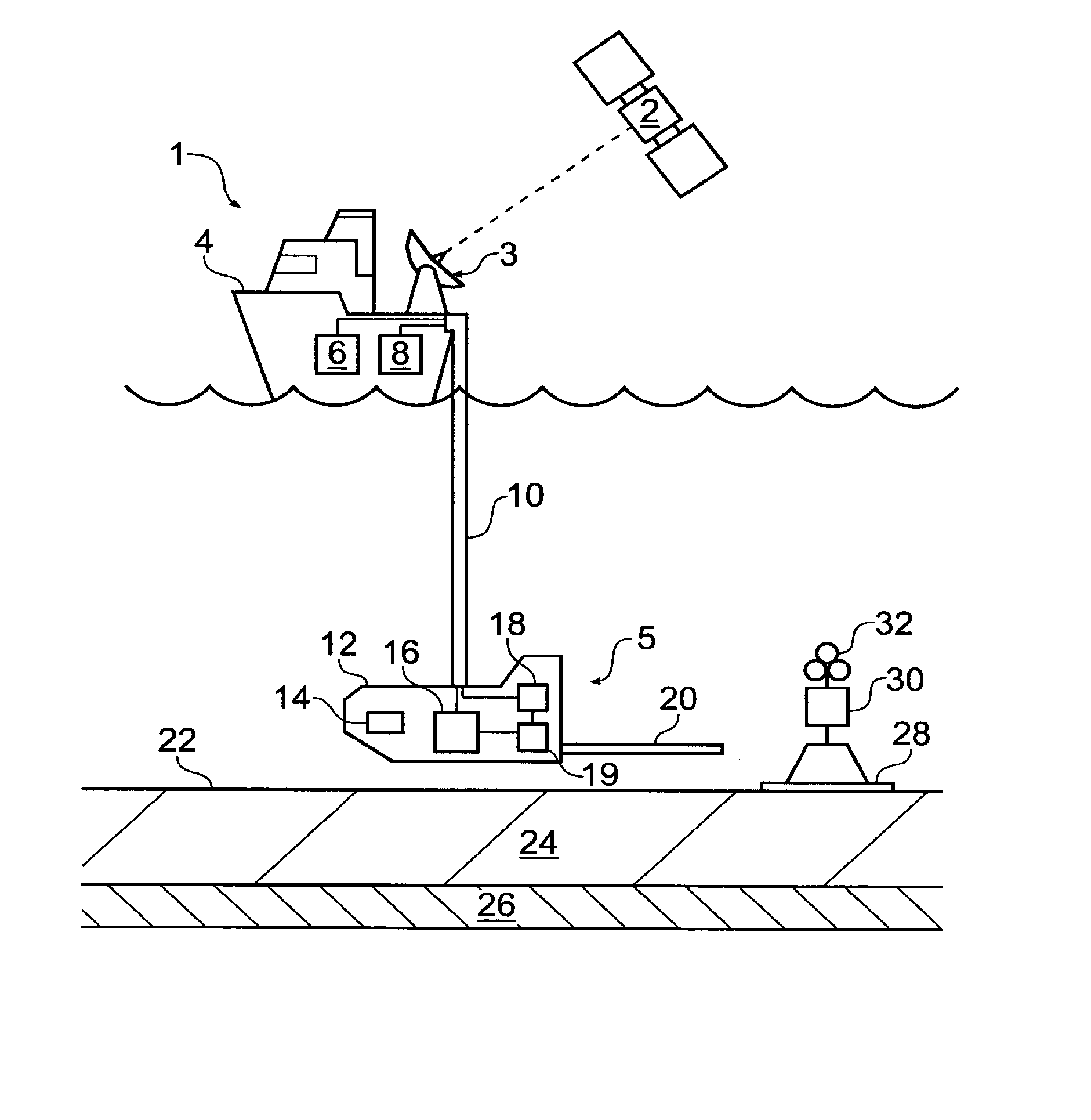
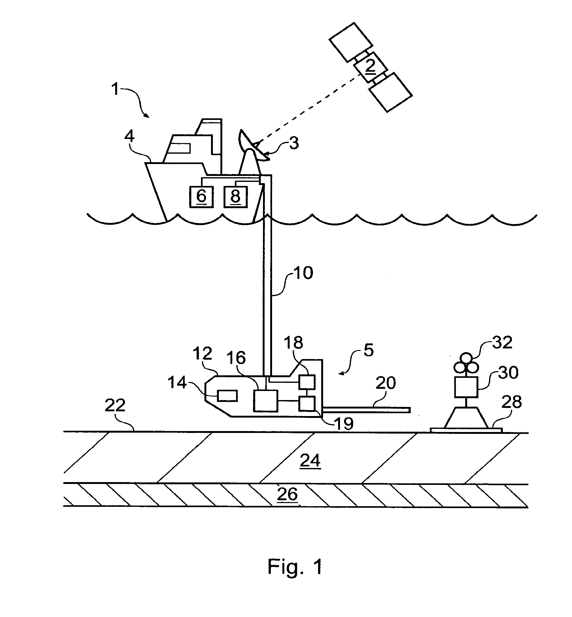
[0024]FIG. 1 shows a seafloor surveying system 1 comprising a submersible EM field generator 5. The EM field generator 5 is carried by a submersible vehicle 12 that is towed by a surface vehicle 4. The submersible vehicle 12 remains at an approximately constant distance above the seafloor 22. This separation is achieved by using an echo location module 14 to measure the distance of the submersible vehicle 12 from the seafloor 22 and to relay information regarding the measured separation to the surface vehicle 4. The depth of the submersible vehicle 12 may then be adjusted by reeling-in or letting-out an appropriate length of the umbilical cable 10, or otherwise (for example, by controlling the submersible vehicle 12 with on board thrusters and / or hydrodynamic surfaces).

[0025] Power and control signals are transmitted from the surface vehicle 4 to the submersible vehicle 12 through the umbilical cable 10, which also provides the mechanical link between the surface vehicle 4 and the ...


PUM


Abstract

A submersible electromagnetic (EM) field generator for seafloor electromagnetic surveying comprising an AC to DC converter operable to generate a DC output from an AC input and a switching module operable to generate a waveform driving signal by selectively switching the DC output. The EM field generator also comprises an antenna that is operable to generate an EM field in response to the waveform driving signal. This design approach of using a switched DC source allows square or rectangular wave EM signals to be generated which have sharp transition characteristics and which are substantially independent of the AC input characteristics.

Description

RELATED APPLICATION DATA [0001] This application is a divisional of U.S. patent application Ser. No. 11 / 169,381 filed Jun. 29, 2005, which is hereby incorporated herein by reference in its entirety.BACKGROUND OF THE INVENTION [0002] The present invention relates to electromagnetic surveying. In particular, the present invention relates to the generation of electromagnetic (EM) fields when surveying for hydrocarbon reservoirs or other formations identifiable by their electrical properties. [0003] Determining the response of the sub-surface strata within the earth's crust to electromagnetic fields is a valuable tool in the field of geophysical research. The geological processes occurring in thermally, hydrothermally or magmatically active regions can be studied. In addition, electromagnetic sounding techniques can provide valuable insights into the nature, and particularly the likely hydrocarbon content, of subterranean reservoirs in the context of subterranean oil exploration and sur...

Claims


Application Information

Patent Timeline
Patent Type & Authority Applications(United States)
IPC IPC(8): G01V3/00H01C7/12H02M7/217G01V3/12
CPCG01V3/12G01V3/083G01V3/165G01V3/17
Inventor MILNE, JAMESRUST, JENNIFERSYKES, CHRISBENNETT, MARK
Owner MILNE JAMES
Why Eureka
Try Eureka