Light emitting device, surface light source device, display and light flux control member

US20080007966A1Active Publication Date: 2008-01-10ENPLAS CORP

Image

  • Light emitting device, surface light source device, display and light flux control member
  • Light emitting device, surface light source device, display and light flux control member
  • Light emitting device, surface light source device, display and light flux control member

Examples


first embodiment

(Skeleton of Surface Light Source Device 2 and Display)

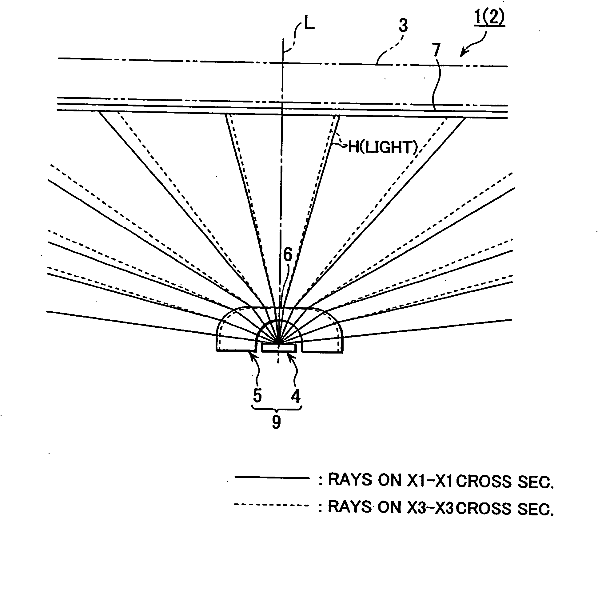
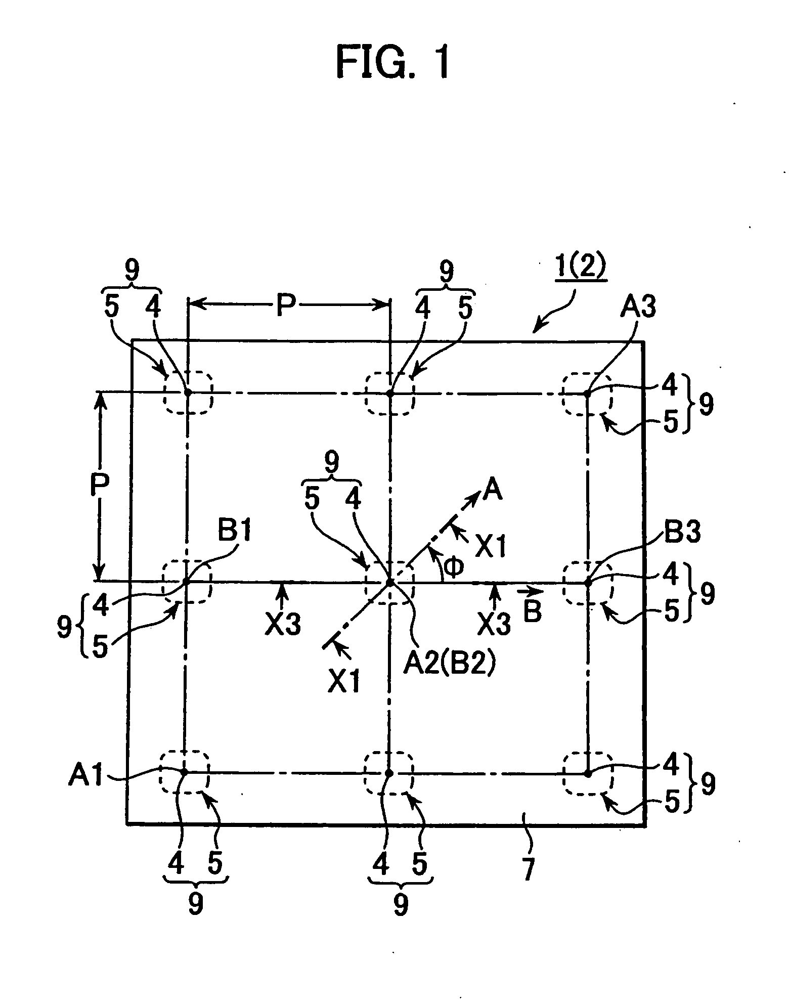
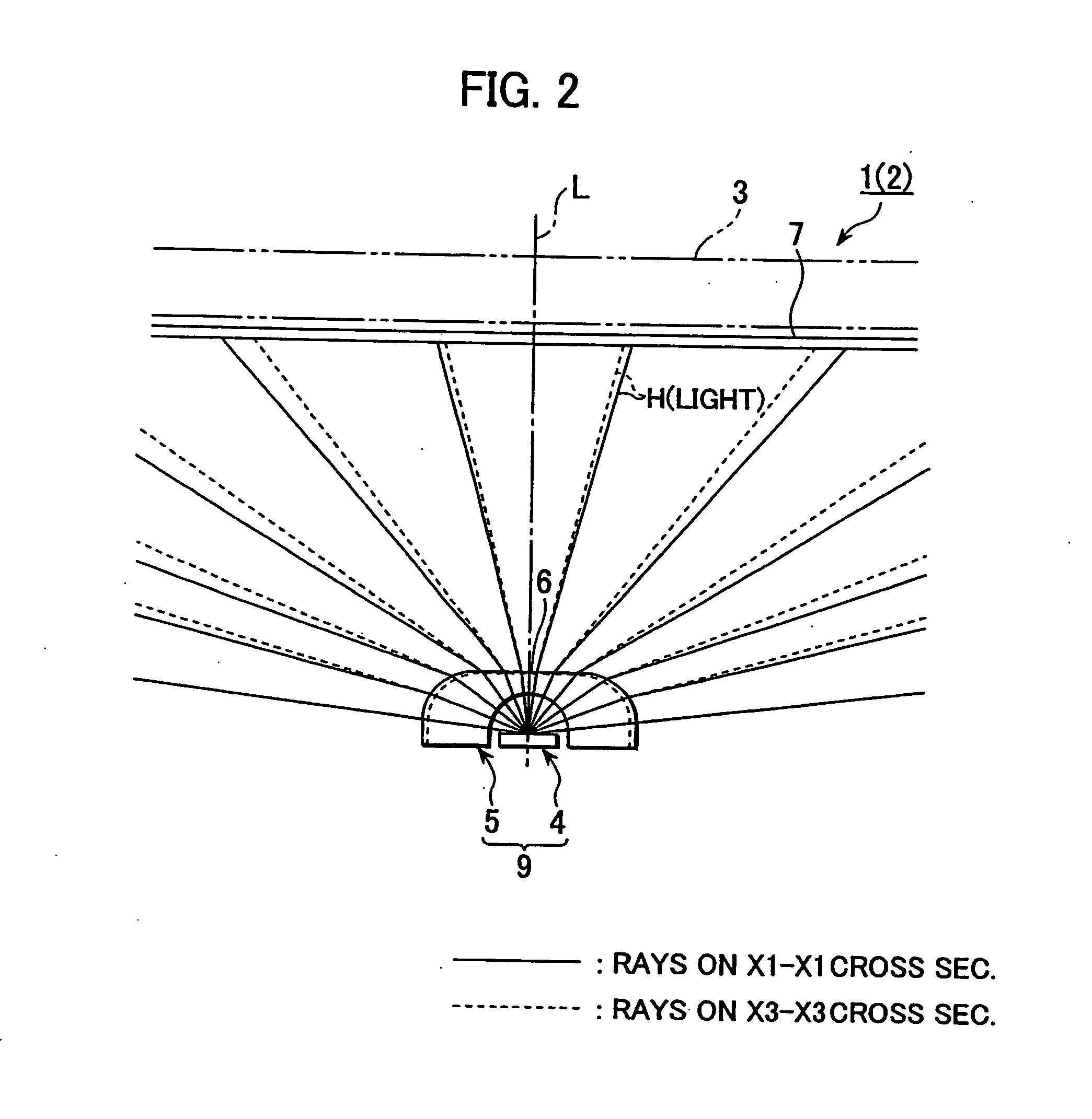
[0070] FIGS. 1 to 3 illustrate display 1 surface light source device 2 included in display 1. FIG. 1 is a plan view of surface light source device 2 and display 1, with a member-to-be-illuminated (displaying member) being omitted. FIG. 2 is a cross sectional diagram for illustrating cross sections along lines XI-XI and X3-X3 in FIG. 1. FIG. 3 is a partial cross section view of display 1 in the, illustrating parameters (such as θ1 , θ3 , θ5) in connection with a datum optical axis L.

[0071] It is noted that “datum optical axis L of light emitting device 9” is defined as “a light traveling direction at a center of a three-dimensional emission flux from light emitting device 9”. On the other hand, “optical axis of light emitting element (point-like light source) 4” is defined as “a light traveling direction at a center of a three-dimensional emission flux from light emitting element 4”. In this embodiment, “datum optical axis L o...

concrete example

[0136] First, described is a concrete example of light emitting device 9 employing light flux control member 5 in accordance with the present invention by referring to FIGS. 4a to 4d. Outline dimensions L1, L2 of light flux control member 5 (emission control face 6), shapes of first and second emission faces 6a, 6b and others shown in these illustrations are designed under consideration of some conditions.

[0137] The conditions may include, for example, light emitting characteristics of light emitting element 4 (such as expanse angle of light emitting element 4 which is expressed by the foresaid “half-intensity-angular-range”), thickness d of light flux control member 5 along a direction of optical axis L (in particular, distance from light emitting face portion 4a of light emitting element 4 to first emission face 6a of emission control face 6 along optical axis L), pitch between individual light emitting elements 4 p , distance L h from emission face 6 (first emission face 6a) to ...

first example

[0156] As shown in FIG. 8a, employed is a sheet-like base material 7a both faces of which processing for giving light diffusion ability, such as emboss-processing or bead-coating, is applied, thereby both faces of light diffusion member 7 made provided with fine uneven configurations 7b, 7b. Such fine uneven configurations 7b, 7b cause light diffusion.


PUM


Abstract

Light from light emitting element enters into a flux control member through a recess on an inner face of the light flux control member, being emitted from an emission control face (outer face). At least so far as light falls within a half-intensity-angular-range, the light satisfies Condition 1 (θ5 / θ1)>1 except for light in the vicinity of a normal direction of the emission control face) and Condition 2 (Value of θ5 / θ1>1 gets smaller gradually with increasing of θ1). It is noted that θ1, θ5 are angles made at being inner-incident to the emission control face and at being emitting from the same, respectively. The emission control face has a planar outline shape which is anisotropic around optical axis L, thereby causing value of θ5 / θ1 to have a change depending on direction angle φ around optical axis L, with the result that highly uniform light is supplied to a required anisotropic irradiation range.

Description

BACKGROUND [0001] 1. Field of Invention [0002] The present invention relates to a light emitting device, surface light source device, display and a light flux control member, being applied, for example, to a light emitting device or surface light source device 2 for backlighting a display member such as LCD-panel, or to a display composed of a display member and such light emitting device or surface light source device. [0003] Further, the present invention is also applied to a light flux control member used in devices as above. More concretely, a light emitting device, surface light source device, display and light flux control member are employable in displays used as TV-monitors or monitors for personal computers and in backlighting arrangements in the devices. In addition, applications to interior illumination or various illumination are possible. [0004] 2. Related Arts [0005] It has been known to employ a surface light source device provided with a light emitting diode (LED) an...

Claims


Application Information

Patent Timeline
10 Jan 2008
Publication
US20080007966A1
IPC
F21V7/04; H01L33/58
CPC
G02B5/045; G02B19/0066; G02B19/0061; G02B19/0028; G02B19/0071
Inventors
OHKAWA, SHINGO