Method of bonding golf club head by brazing

Inactive Publication Date: 2008-01-10
CHEN ARCHER C C
View PDF3 Cites 15 Cited by
  • Summary
  • Abstract
  • Description
  • Claims
  • Application Information

AI Technical Summary

Benefits of technology

[0005]The primary objective of the present invention is to provide a method of bonding a golf club head, which improves the brazing quality.
[0006]The secondary objective of the present invention is to provide a method of bonding a golf club head, which simplifies the brazing process.

Problems solved by technology

Some brazing solders act on the metal in brazing process to change the structure, material property of the metal, further more, it may break the metal.

Method used


Image

  • Method of bonding golf club head by brazing
  • Method of bonding golf club head by brazing
  • Method of bonding golf club head by brazing

Examples


Embodiment Construction

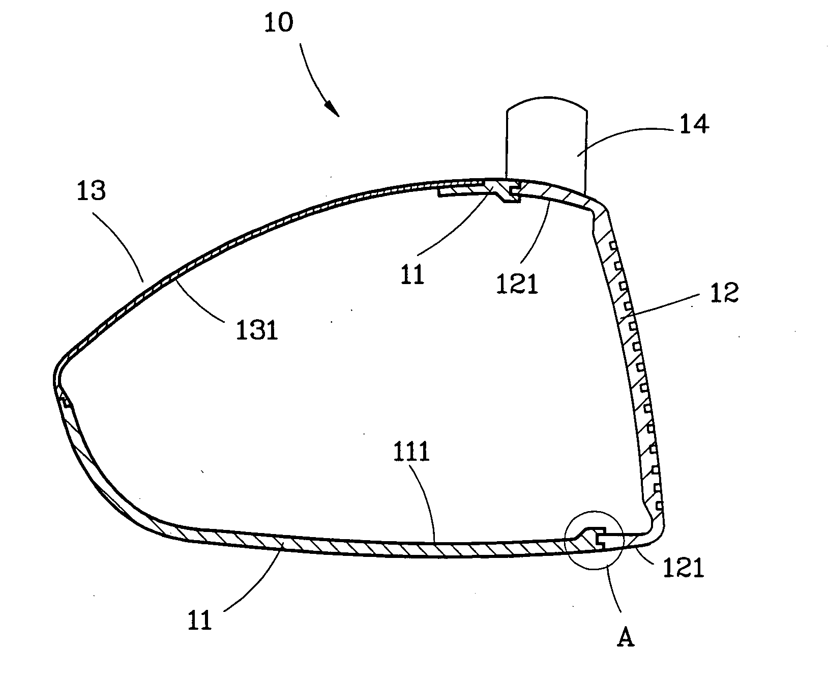
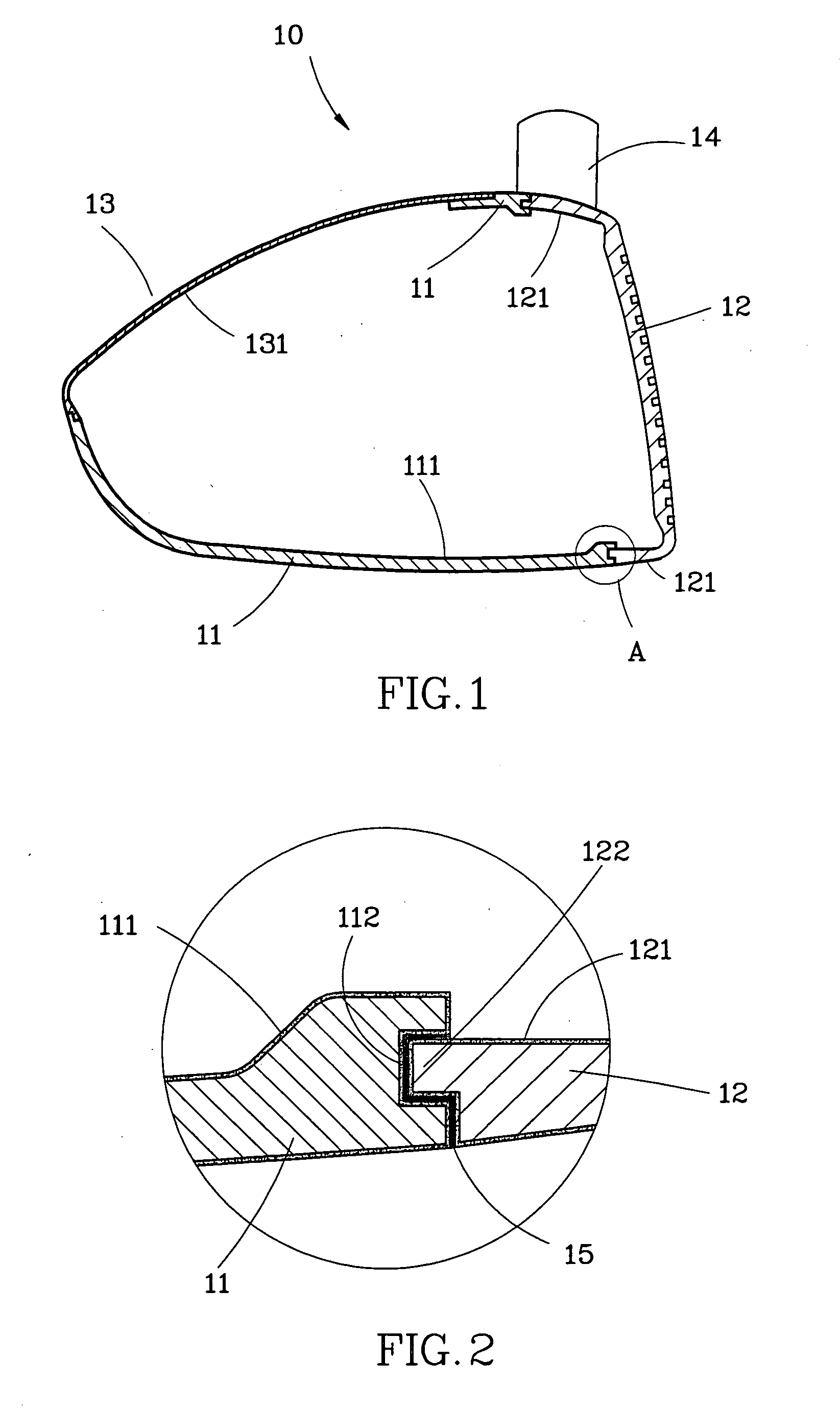
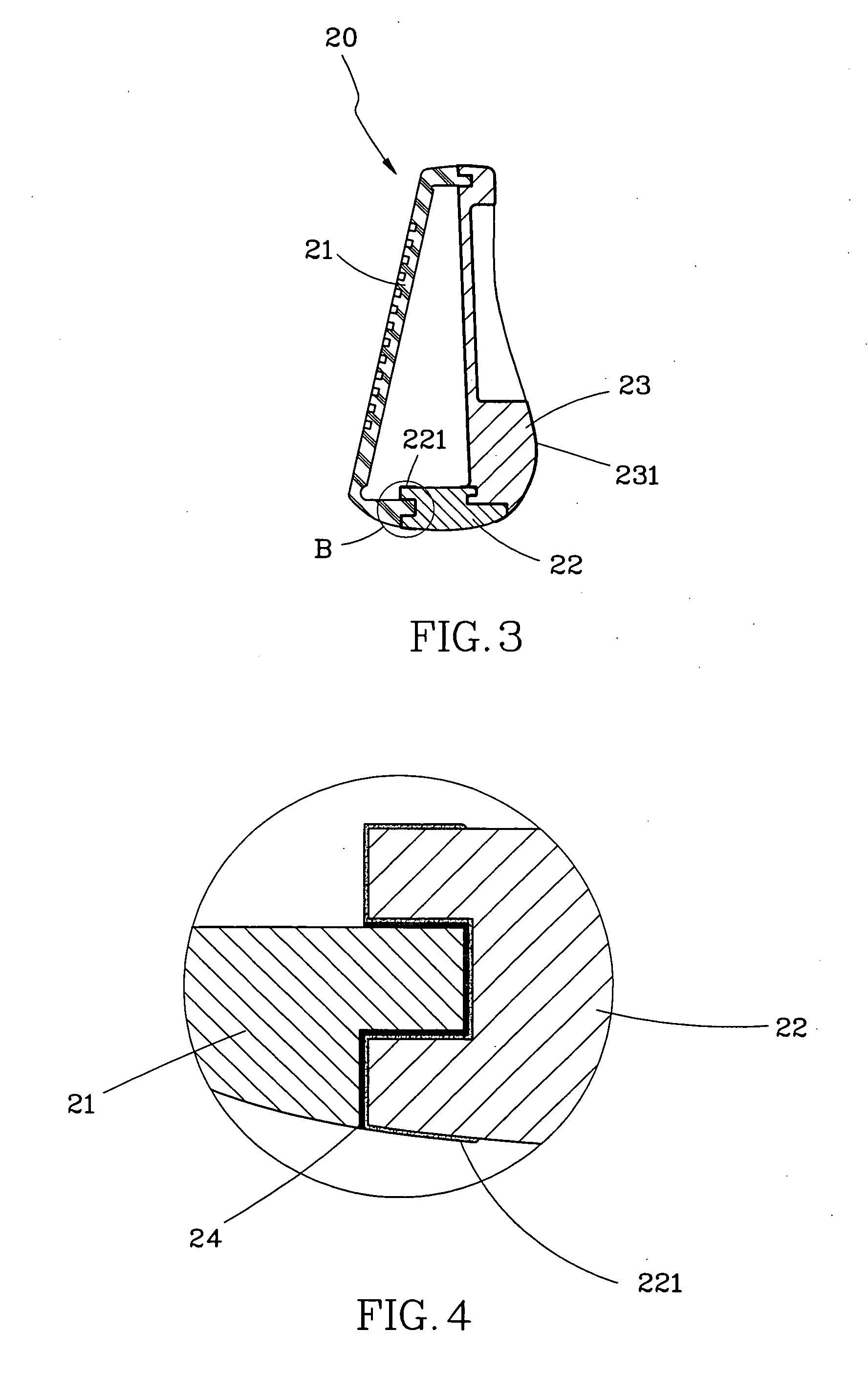
[0012]As shown in FIG. 1, a wood golf club head 10 of the first preferred embodiment of the present invention consists of a main member 11, a face member 12 and a crown 13. The main member 11 includes a neck 14. The face member is a cup-like member, and the crown is a thin metal plate. The main member 11 and the crown 13 are provided with a metal skin layer 111, 131 respectively, and the face member is provided with a metal skin layer 12 on a bonding portion thereof. These metal skin layers may form protective layers to bar air from the components 11, 12, and 13 so that they won't be oxidized. The components 11, 12, and 13 are bonded together by brazing to form the golf club head 10.

[0013]As shown in FIG. 2, the main member 11 is provided with a slot 112, in which a solder is provided, on the bonding portion, and the face member 12 is provided with a protrusion 122 to be inserted into the slot 112. The golf club head 10 is heated in a vacuum stove to solidify the solder so that the ...


PUM


Abstract

A method of making a golf club head, which the golf club includes a plurality of components, includes the steps of: coating a brazing solder on the components, then heating the components for solidification of the brazing solder to form a metal skin layer on each component, then bonding the components together by brazing.

Description

BACKGROUND OF THE INVENTION[0001]1. Field of the Invention[0002]The present invention relates generally to a method of making golf-clubs, and more particularly to a method of bonding the components of a golf club head by brazing.[0003]2. Description of the Related Art[0004]U.S. Pat. No. 5,871,408 disclosed a method of bonding the components of a golf club head by brazing. In manufacture of golf clubs, components of the golf club are made by casting or forging. These components usually are stored in a warehouse prior to assembly. Welding is the most common technique in assembly of the golf clubs. The components usually are oxidized after welding, and the material property will change. For example, stainless, which is the common material to make the golf club head, will act on oxygen in the air to form a chromium oxide (Cr2O3) film on the surface, and the film makes a weak bonding strength between the brazing solder and stainless. It usually has to perform surface treatment, including...

Claims


Application Information

Patent Timeline
IPC IPC(8): A63B53/00
CPCA63B53/0466A63B53/047A63B2053/0437A63B2053/0433B23K1/0008A63B53/0433A63B53/0437
Inventor CHEN, ARCHER C.C.
Owner CHEN ARCHER C C
Why Eureka
Try Eureka