Device and method for treating compression fractures

a compression fracture and device technology, applied in the field of implantable medical devices, can solve the problems of pain, spinal instability, paralysis, and current treatment of vertebral compression fractures with respect to fractures of cancellous bone, and achieve the effect of reducing a first location of fracture and a second location of fractur

Inactive Publication Date: 2008-01-10
GOTFRIED BRUCE +1
View PDF6 Cites 48 Cited by
  • Summary
  • Abstract
  • Description
  • Claims
  • Application Information

AI Technical Summary

Benefits of technology

[0016]Typically, the implant is non-inflating, and instead comprises a solid object which is unfolded or unrolled as part of its expansion. For example, the implant may comprise a sheet of metal (or another strong, flexible material) that in its compressed state is coiled like a scroll. The sheet of material may have flat or planar major sides. In one embodiment, the implant comprises a chrome-based stainless steel, such as 316 stainless steel, cobalt chrome, or a titanium-based alloy (e.g., nitinol). For some applications, the implant is thermally treated and / or has one or a plurality of holes passing therethrough that make the implant more flexible and thereby allow it to be easily manipulated. In any case, the expansion tool may typically be coupled to an inside edge region of the coiled sheet of metal and rotated in order to apply a force to the inside edge of the implant that causes the implant to expand, i.e., to increase its outer radius to a final radius deemed suitable by the physician to support the vertebral body in which it is implanted.
[0018]If it is desired to reposition or remove the implant following the expansion thereof, the tool can typically, but not necessarily, be operated in a reverse direction in order to compress the implant and facilitate the repositioning or removal of the implant. For some applications, removal of the implant is performed in a follow-up procedure, by re-coupling the expansion tool to the implant, or coupling a different tool to the implant, and reducing the size of the implant using the tool.
[0035]There is yet further provided, in accordance with an embodiment of the invention, a method for treating a bone with a compression fracture, including inserting a device in a compressed state into a first site of the bone, expanding the device under physician control while the device is in the bone, to reduce a first location of the fracture, compressing the device while the device is in the bone, moving the device within the bone to a second site, and expanding the device under physician control while the device is at the second site, to reduce a second location of the fracture.

Problems solved by technology

Yet age, disease, and trauma can cause structural failures of the spinal column arising from, for example, vertebral fractures, disc hernias, and degenerative disc diseases.
Such pathologies may result in pain, spinal instability, and paralysis.
In many instances, current treatments of vertebral compression fractures are not fully successful with respect to fractures of cancellous bone.
Additionally, fractures in the thoracic and lumbar spine are common, particularly in elderly patients who suffer from weak, osteoporotic bones.
Known treatments for many of these fractures are not fully satisfactory.

Method used


Image

  • Device and method for treating compression fractures
  • Device and method for treating compression fractures
  • Device and method for treating compression fractures

Examples


Embodiment Construction

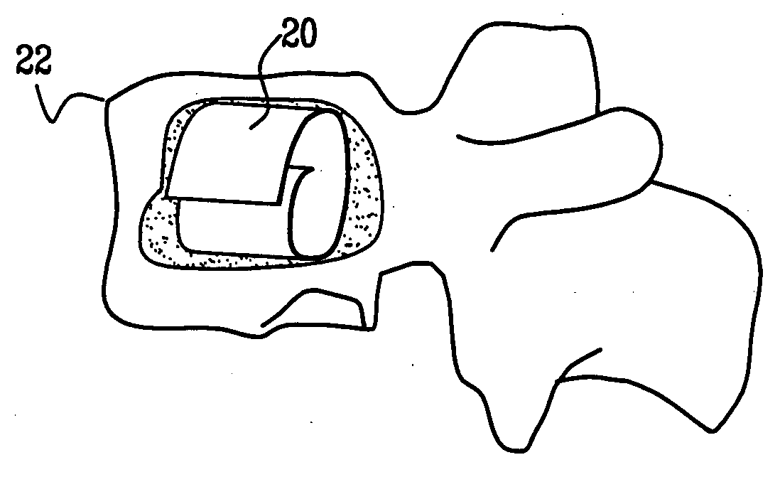
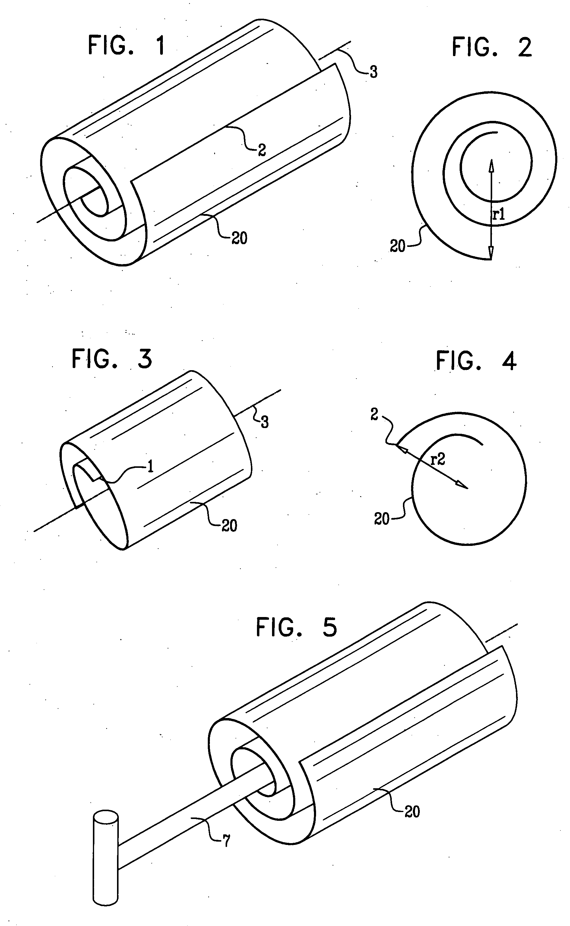
[0046]Referring to the accompanying drawings wherein like reference numerals refer to the same or similar elements, FIGS. 1 and 2 are schematic illustrations of a vertebral body implant 20 in a compressed state thereof, in accordance with an embodiment of the present invention, FIG. 2 being a cross-sectional view of the implant shown in FIG. 1. A distance r1 between an outer edge 2 and a longitudinal axis 3 of the implant is typically between about 2 mm and about 5 mm, for example about 2.5 mm. Prior to being rolled into the shape shown in FIG. 1, the dimensions of the implant are typically between about 0.1 mm and about 0.5 mm thick (e.g., about 0.2 mm), between about 10 mm and 30 mm wide (e.g., about 20 mm), and between about 50 mm and about 150 mm long (e.g., about 90 mm).

[0047]In general, the size of implant 20 is selected based on the patient's physiology. The implant 20 typically comprises a strong, flexible, biocompatible material. In one embodiment, the implant 20 comprises ...


PUM


Abstract

Apparatus for treating a bone with a compression fracture, includes a coil having a compressed state and an expanded state and which is insertable into the bone when in its compressed state, and an expansion tool arranged to be coupled to the coil when the coil is present in the bone. Manual control of the expansion tool, e.g., by a physician, enables expansion of the coil from the compressed state to the expanded state. Methods for using the apparatus are also described.

Description

CROSS REFERENCE TO RELATED APPLICATION[0001]This application claims priority of U.S. provisional patent application Ser. No. 60 / 806,735 filed Jul. 7, 2006, incorporated by reference herein.FIELD OF THE INVENTION[0002]The present invention relates generally to implantable medical devices, and specifically to methods and devices for treatment of compressive bone fracture or diseased bone, such as a fractured vertebra.BACKGROUND OF THE INVENTION[0003]The spinal column serves as the support structure for the body, giving the body its posture. Yet age, disease, and trauma can cause structural failures of the spinal column arising from, for example, vertebral fractures, disc hernias, and degenerative disc diseases. Such pathologies may result in pain, spinal instability, and paralysis.[0004]The spinal column includes 26 vertebrae. A typical vertebra consists primarily of two parts—an anterior segment comprising the body of the vertebra, and a posterior segment comprising the vertebral or ...

Claims


Application Information

Patent Timeline
Patent Type & Authority Applications(United States)
IPC IPC(8): A61B17/58A61B17/56
CPCA61B17/8858A61B17/70
Inventor GOTFRIED, BRUCEGOTFRIED, YECHIEL
Owner GOTFRIED BRUCE
Why Eureka
Try Eureka