
Treatment of Skin by Spatial Modulation of Thermal Heating

a spatial modulation and thermal heating technology, applied in the field of skin treatment using radiation, can solve the problems of ablative resurfacing having undesirable post-treatment side effects, permanent scarring is a possible long-term side effect of ablative resurfacing, and the sub-surface methods are less dramatic than those achieved by ablative resurfacing

Inactive Publication Date: 2008-01-10
CANDELA CORP
View PDF124 Cites 20 Cited by
  • Summary
  • Abstract
  • Description
  • Claims
  • Application Information

AI Technical Summary

Benefits of technology

[0007] A beam of radiation can have a modulated spatial profile such that the fluence, the intensity, and / or the wavelength delivered to the skin can be varied. The spatial profile determines the depth of thermal injury to the skin. A beam of radiation can be delivered to a region of skin to cause modulated spatial profile of temperature, such that the depth of damage to the skin is varied. An advantage of the invention is that a large target region can be formed with damaged regions adjacent to substantially undamaged regions within the target region, together with a substantially continuous surface thermal injury. The substantially undamaged regions can be undamaged or less damaged than the damaged regions. Other advantages include: improved treatment efficacy initiating from zones corresponding to deeper first damage zones, high coverage of a treatment region corresponding to deeper first damage zones and less deep second damage zones, improved efficacy relating to forming a substantially continuous surface thermal injury, and improved post-treatment healing initiating from zones corresponding to less deep second damage zones.

Problems solved by technology

However, ablative resurfacing can have undesirable post-treatment side effects.
Furthermore, permanent scarring is a possible long-term side effect of ablative resurfacing.
However, the results of sub-surface methods can be less dramatic than those achieved by ablative resurfacing.

Method used


Image

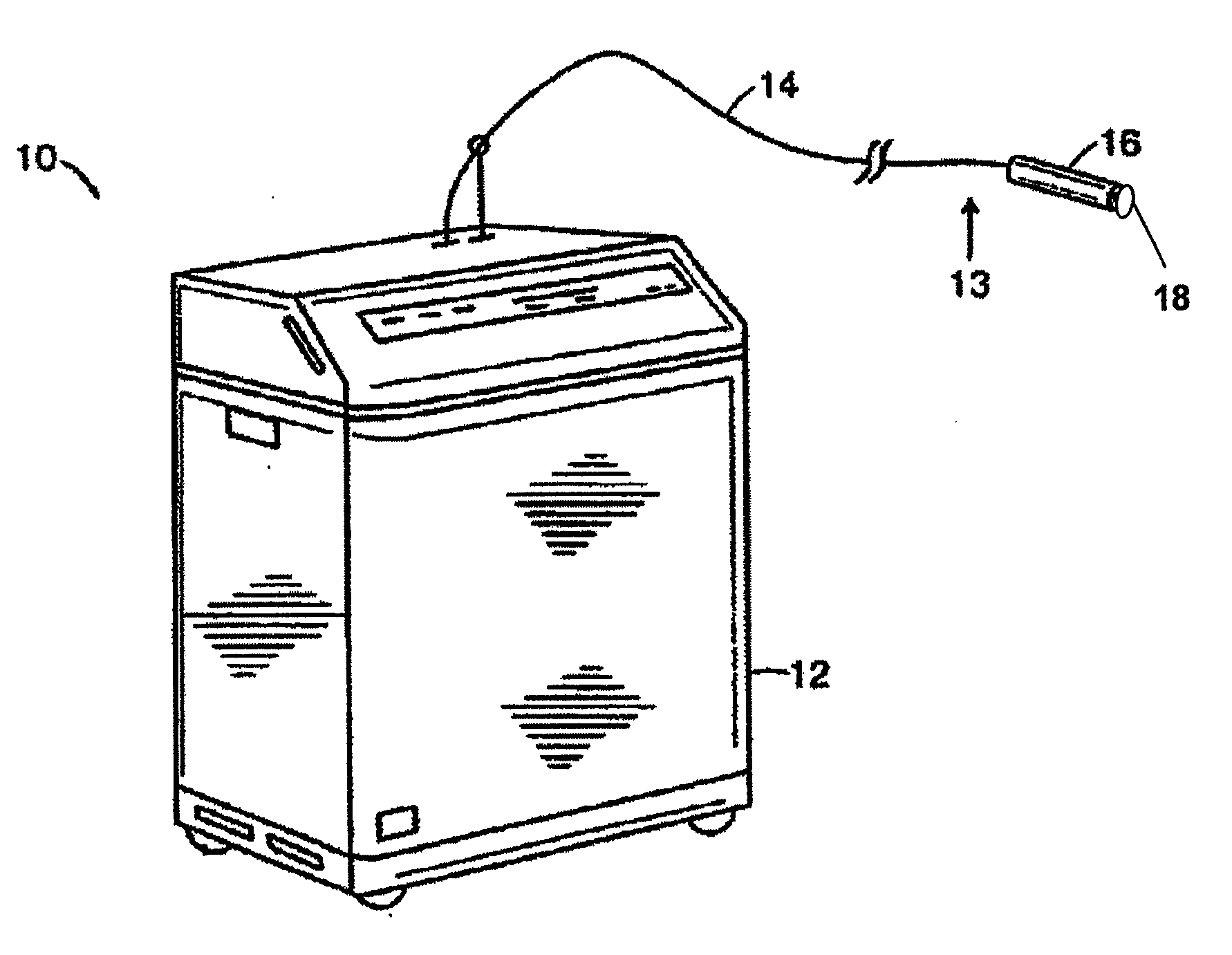
  • Treatment of Skin by Spatial Modulation of Thermal Heating
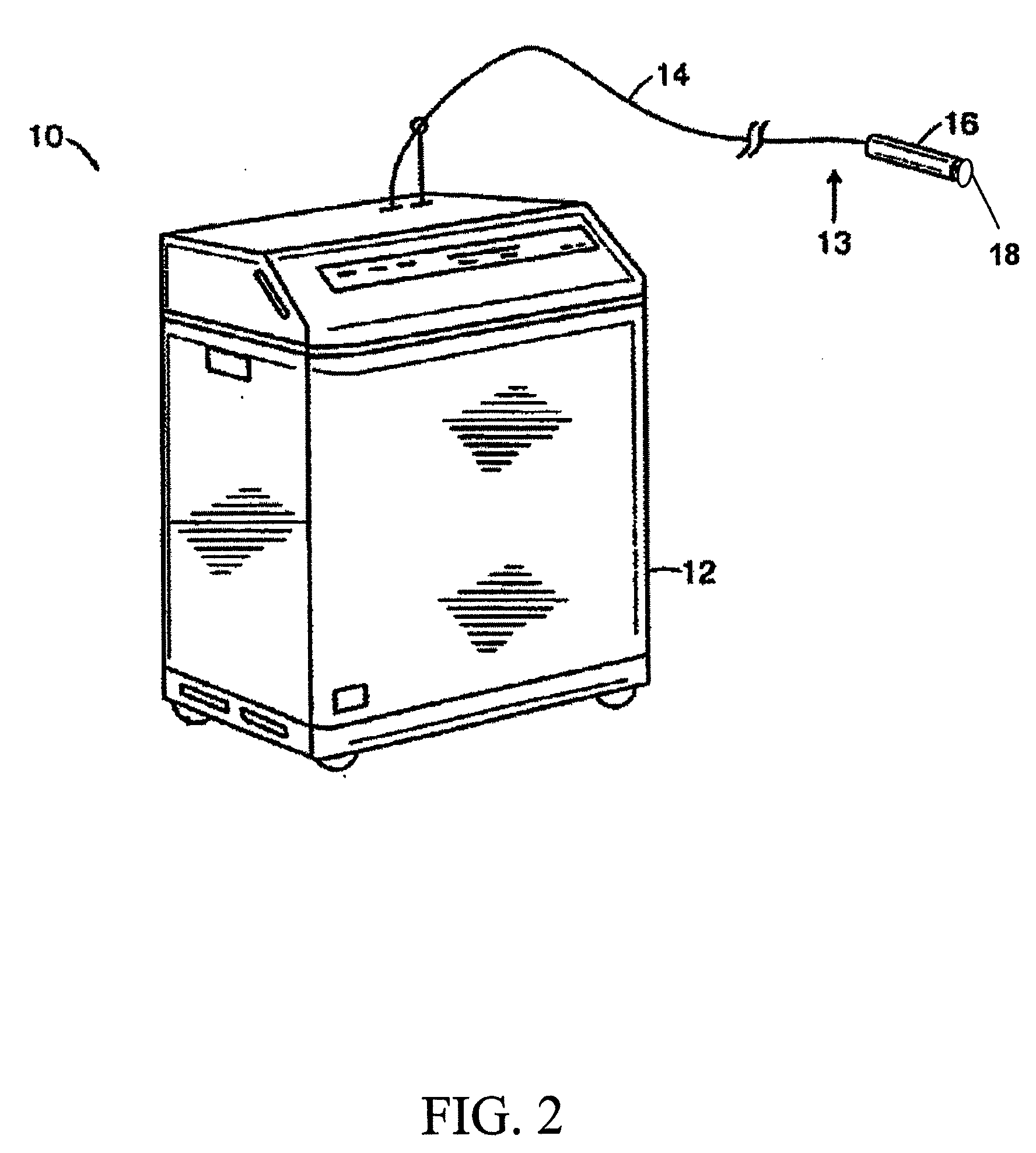
  • Treatment of Skin by Spatial Modulation of Thermal Heating
  • Treatment of Skin by Spatial Modulation of Thermal Heating

Examples


Embodiment Construction

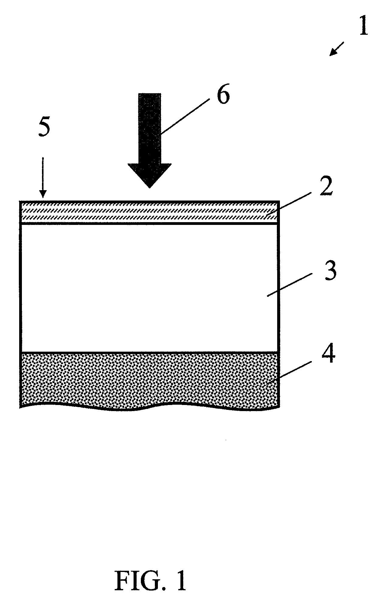
[0032]FIG. 1 shows an exemplary cross-section of skin 1 including a region of epidermis 2, a region of dermis 3, a region of subcutaneous tissue 4, and a surface of the skin 5. In one embodiment, the skin 1 can be a region of human skin with wrinkles. A beam of radiation 6 can be delivered to the skin 1 to treat at least a region of skin, including a region of epidermis 2 and / or a region of dermis 3. Skin treatments can include skin rejuvenation and treatments for wrinkles, vessels, pigmentation, scarring, and acne.

[0033] A therapeutic injury can be induced with electromagnetic radiation in the visible to infrared spectral region. A wavelength of light that penetrates into at least a portion of skin can be used. Chromophores can include blood (e.g., oxyhemoglobin and deoxyhemoglobin), collagen, melanin, fatty tissue, and water. Light sources can include lasers, light emitting diodes, or an incoherent source, and can be either pulsed or continuous. In one embodiment, a light source ...


PUM


Abstract

Treating skin can include delivering a beam of radiation to a target region of the skin to cause a zone of thermal injury including a lateral pattern of varying depths of thermal injury distributed along the target region. The lateral pattern includes at least one first sub-zone of a first depth of thermal injury laterally adjacent to at least one second sub-zone of a second depth of thermal injury. The first depth is greater than the second depth. The at least one first sub-zone of the first depth and the at least one second sub-zone of the second depth extend from a surface of the target region of the skin to form a substantially continuous surface thermal injury. The at least one first sub-zone of the first depth and the at least one second sub-zone of the second depth are substantially heated to at least a critical temperature.

Description

CROSS-REFERENCE TO RELATED APPLICATION [0001] This application claims the benefit of and priority to U.S. Provisional Application Ser. No. 60 / 813,729 filed Jun. 14, 2006, which is owned by the assignee of the instant application and the disclosure of which is incorporated herein by reference in its entirety.FIELD OF THE INVENTION [0002] The invention relates generally to a skin treatment using radiation. In particular, the invention relates to a method for treating skin using a beam of radiation to cause spatially modulated thermal injury of the skin sufficient to elicit a healing response and improvement in the skin. BACKGROUND OF THE INVENTION [0003] Ablative resurfacing of skin with lasers can be an effective treatment for skin conditions such as wrinkles. However, ablative resurfacing can have undesirable post-treatment side effects. For example, crusting, oozing, erythema can last up to 5 weeks. Furthermore, permanent scarring is a possible long-term side effect of ablative res...

Claims


Application Information

Patent Timeline
Patent Type & Authority Applications(United States)
IPC IPC(8): A61F7/00A61B18/18
CPCA61B18/203A61B2018/00005A61B2018/208A61B2018/00452A61B2018/00458A61B2018/00029
Inventor PAITHANKAR, DILIP Y.BHAWALKAR, JAYANT D.HSIA, JAMES C.
Owner CANDELA CORP
Learn More