

Control device of variable damping force damper
- Summary
- Abstract
- Description
- Claims
- Application Information
AI Technical Summary
Benefits of technology
Problems solved by technology
Method used
Image

Examples
Embodiment Construction
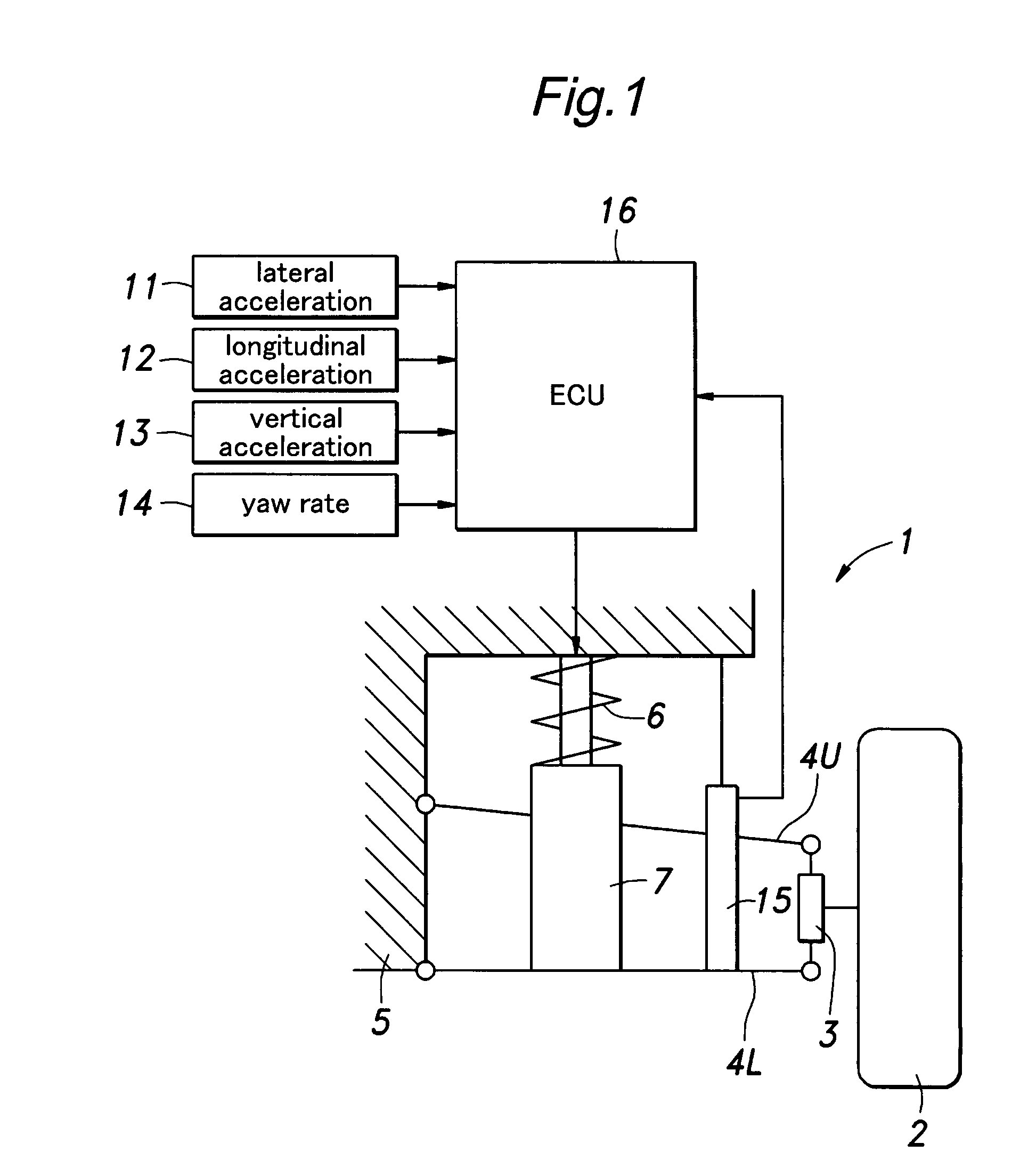
[0027]FIG. 1 shows an example of a basic structure of a motor vehicle suspension system for supporting a vehicle body on left and right, front and rear wheels of a four-wheel vehicle. This suspension system 1 comprises a knuckle 3 for supporting a wheel 2, upper and lower suspension arms 4U, 4L for supporting the knuckle 3 so as to be moveable upward and downward with respect to the vehicle body 5, and a compression coil spring 6 and hydraulic damper 7 provided in parallel between the lower suspension arm 4L and the vehicle body 5.
[0028]The hydraulic damper 7 may consist of a variable damping force damper that is sealingly filled with an MRF (Magneto-Rheological Fluid), for example. In the damper 7, the MRF flows between a piston upper chamber and a piston lower chamber through an orifice provided to the piston as the piston moves up and down and the damper 7 expands and contracts, and an apparent viscosity of the MRF can be changed by controlling an electric current applied to an M...
PUM
 Abstract
Description
Claims
Application Information