Method and device for cleaning the air intake system of a diesel vehicle

Inactive Publication Date: 2008-01-17
BG PRODS
View PDF9 Cites 8 Cited by
  • Summary
  • Abstract
  • Description
  • Claims
  • Application Information

AI Technical Summary

Benefits of technology

[0012] The present invention includes a method, an apparatus and a cleaning solution that provide for the cleaning of air intake system and the EGR valve of a diesel engine having an EGR system, while avoiding many of the problems inherent in the prior art. In short, the apparatus causes a pressure drop within the diesel engine's air intake system. The pressure drop increases the velocity of the air flowing through the system. The increased air velocity artificially increases the vacuum and helps carry the cleaning solution, which is injected into the air stream, throughout the air intake system, thereby completely cleaning the system without the need to manually scrape off any deposits. T

Problems solved by technology

The apparatus also creates additional turbulence

Method used


Image

  • Method and device for cleaning the air intake system of a diesel vehicle
  • Method and device for cleaning the air intake system of a diesel vehicle
  • Method and device for cleaning the air intake system of a diesel vehicle

Examples


Example

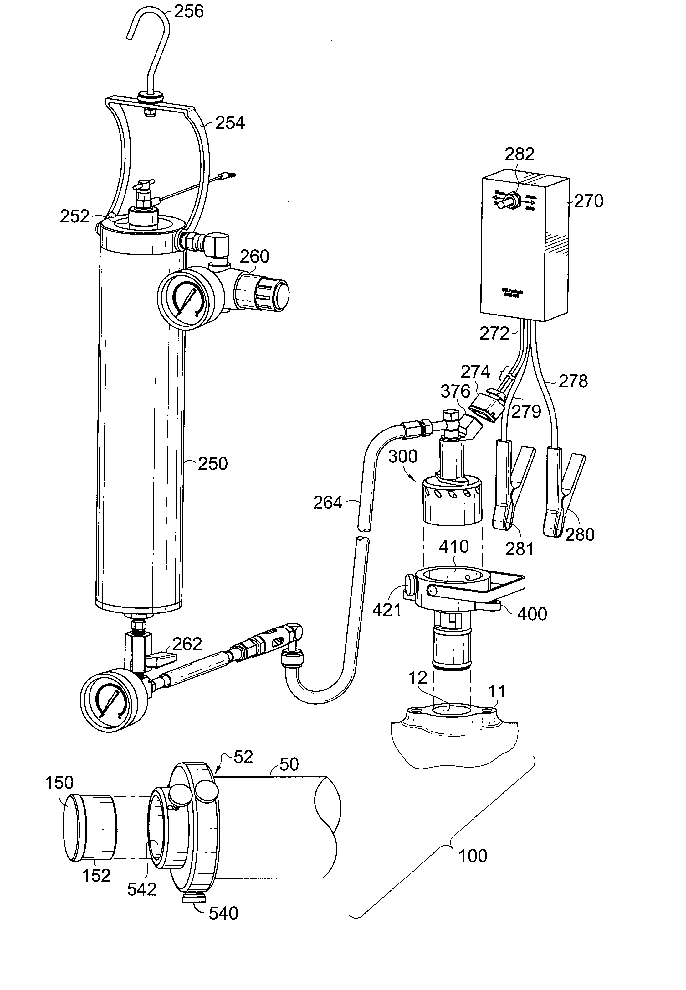
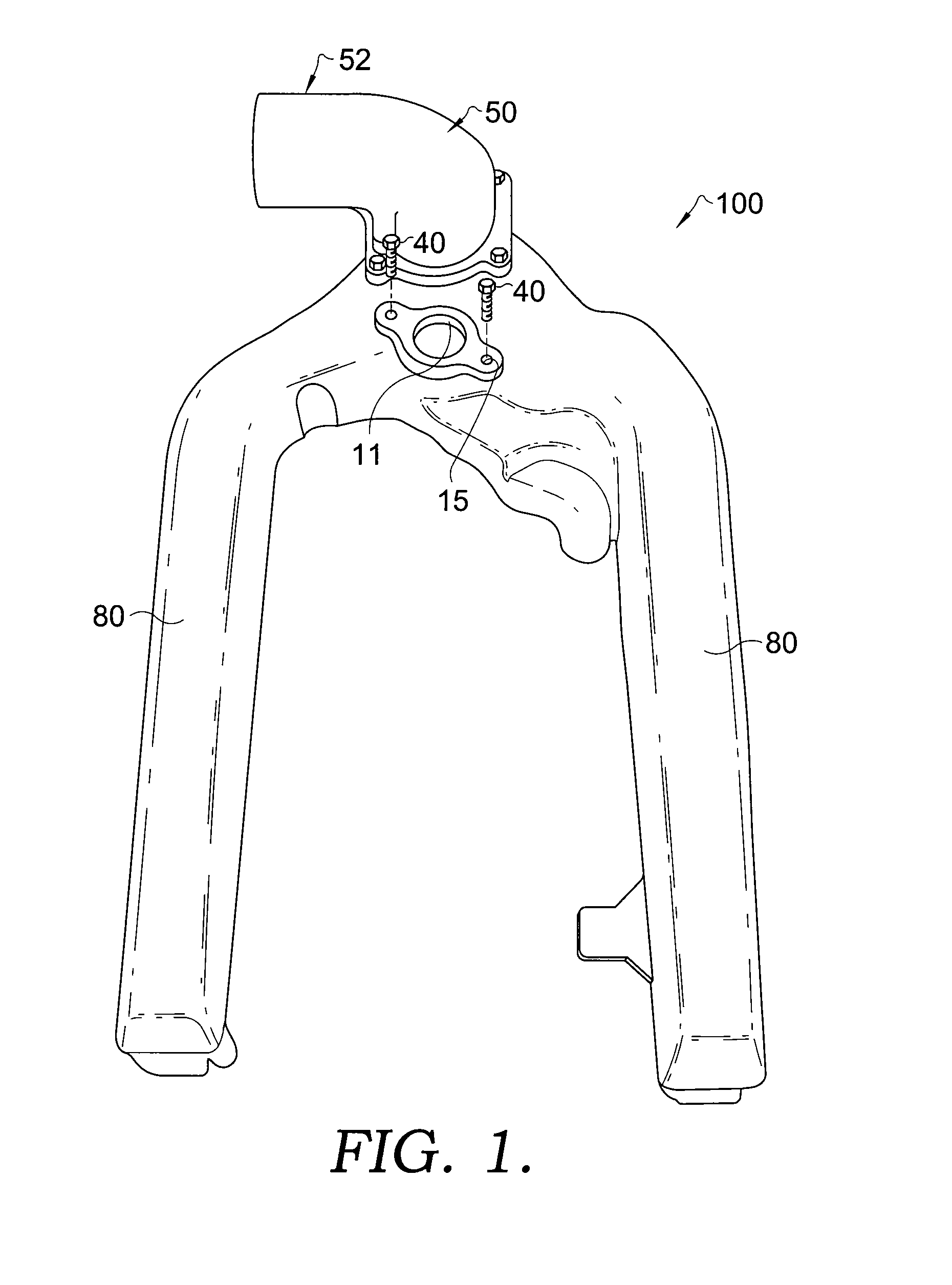
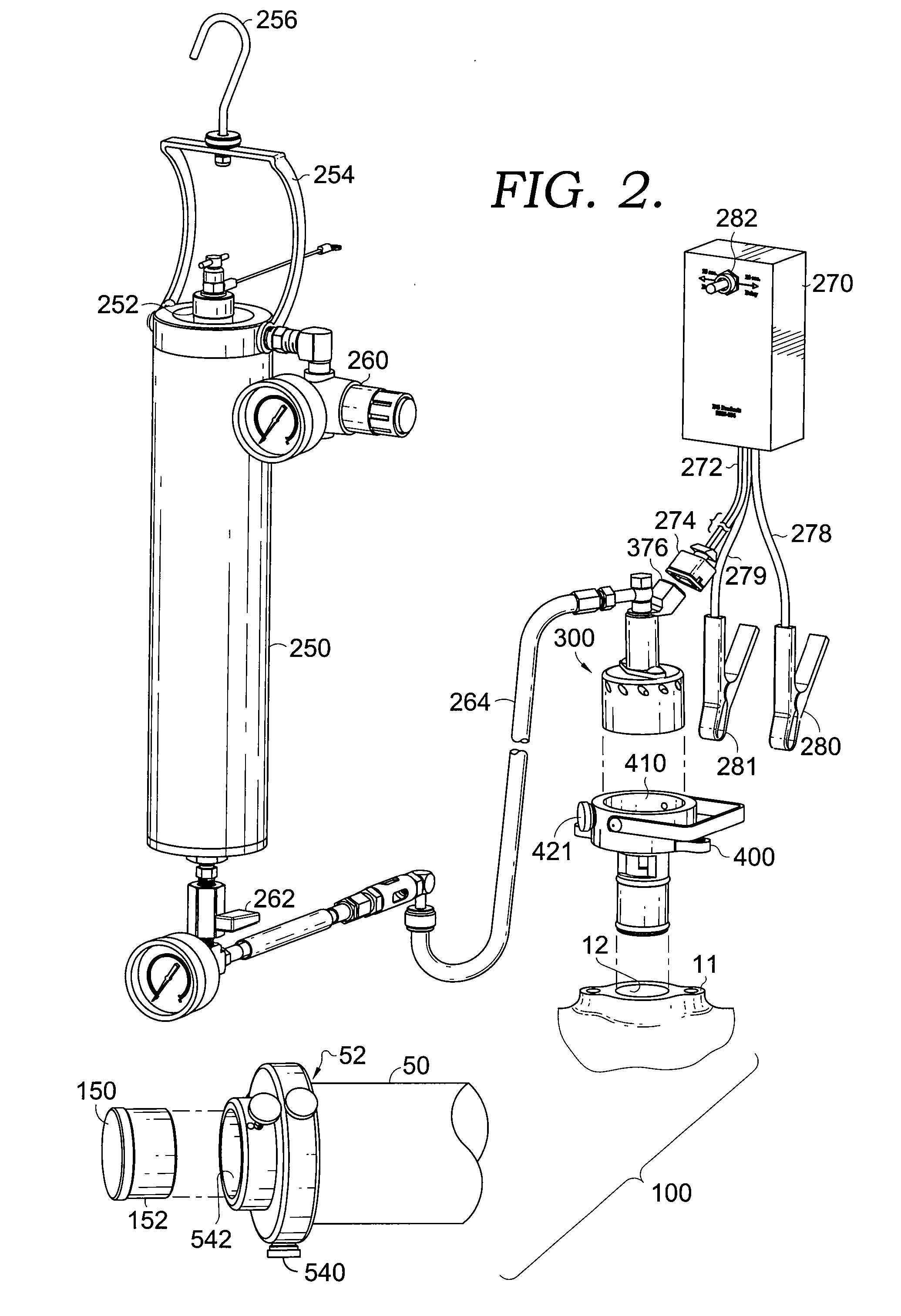
[0028] The present invention includes an apparatus that allows a user to clean the air intake system 100 of a diesel engine (not shown) having an EGR system and avoid the problems inherent in the prior art. The apparatus causes a pressure drop within the diesel engine's air intake system 100, thereby increasing the velocity of the air flowing through the system. The increased air velocity helps carry a cleaning solution, which is injected into the air stream, throughout the air intake system. As a result the entire air intake system is cleaned without the need to manually scrape off deposits.

[0029] The decrease in pressure within the air intake system 100 is created by limiting the amount of air the engine is allowed to draw in while running. This is done by plugging one of the normally two air-intake system openings and placing a vacuum control device 300 on the other opening. While the engine is running, cleaning solution (not shown) is injected into the vacuum control device 300...


PUM


Abstract

A device and method for cleaning the air-intake system of an EGR-valve-equipped diesel engine includes a dispersion component which mixes air and a liquid cleaning solution before delivering them to the air intake system of a running diesel engine. A main air intake is blocked and the EGR valve is removed and replaced with a coupler that receives the dispersion component, whereby a pressure drop is created. The pressure drop creates sufficient vacuum so that cleaner may be administered into the air-intake duct of the running engine. The cleaning solution is provided to the dispersion component under pressure supplied by a pressurized air source.

Description

CROSS-REFERENCE TO RELATED APPLICATIONS [0001] This application, having attorney docket number BGPI.133819, is a continuation-in-part of pending application Ser. No. 10 / 722,302, attorney docket number BGPI.108186, filed Nov. 25, 2003, which claims the benefit of U.S. Provisional Application No. 60 / 478,582, filed Jun. 13, 2003. All of the aforementioned applications are incorporated by reference herein.STATEMENT REGARDING FEDERALLY SPONSORED RESEARCH OR DEVELOPMENT [0002] Not applicable. BACKGROUND OF THE INVENTION [0003] 1. Field of the Invention [0004] The present invention relates generally to the field of cleaning the engine systems of diesel vehicles. More specifically, the present invention relates to a method of cleaning the air intake systems of diesel vehicles. Even more specifically, the present invention relates to the use of a device to introduce carefully controlled amounts of cleaning solution into the air supply system such that the entire air supply system is cleaned....

Claims


Application Information

Patent Timeline
IPC IPC(8): B08B9/043B08B9/02B08B9/04B08B9/045
CPCB08B9/045B08B9/021
Inventor ERWIN, HAROLD E.AUGUSTUS, RICHARD
Owner BG PRODS
Why Eureka
Try Eureka