
Horizontal bulk oil separator

Active Publication Date: 2008-01-17
SHI APD CRYOGENICS +1
View PDF13 Cites 37 Cited by
  • Summary
  • Abstract
  • Description
  • Claims
  • Application Information

AI Technical Summary

Benefits of technology

[0017]Accordingly, it is an object of the present invention to provide a horizontal bulk oil separator which is an integral separator-reservoir which is simpler to construct. In accordance with the invention, the separator is also a reservoir.
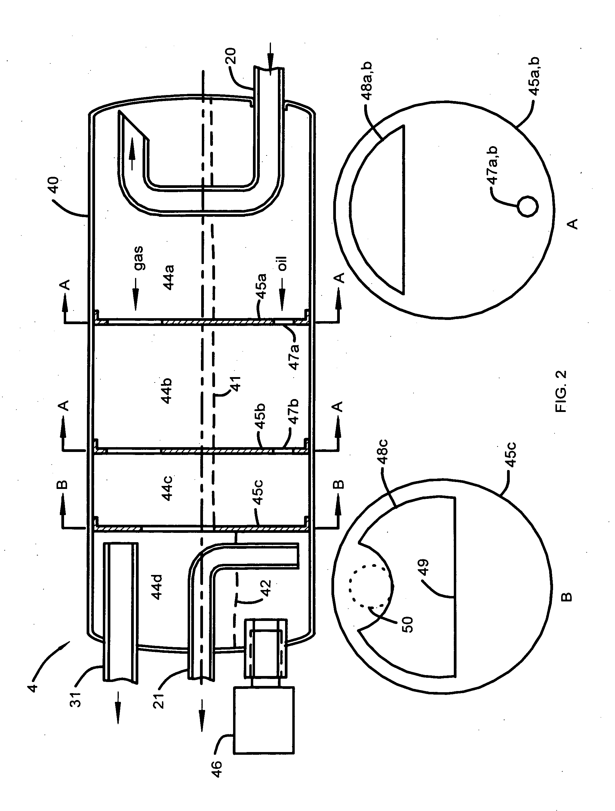
[0024]The helium and oil flow into the bulk oil separator and impinge on the head of the bulk oil separator. Most of the oil drops into the first section of the separator. In a bulk oil separator having an outside diameter of 1.015 cm oil is retained at a depth of 5 cm in three sections that are separated by baffles that have cut-outs for gas above the oil and ports below the oil for oil to flow from section to section. More oil is removed from the gas as it impinges on successive baffles. The last baffle does not have ports for the oil so it is forced to spill over the last cut-out for the gas into the last section which has an oil level switch. These sections allow gas bubbles to rise from the oil so that the oil that spills over into the last section is free of bubbles that would otherwise introduce an error in an opto-electronic type oil level switch. The oil level drops from 7.5 cm to 5 cm as 270 ml of oil is transferred to the adsorber over many years, i.e. more than 5 years, then drops only in the last section, with the level sensor, to 3.5 cm as an additional 30 ml of oil is transferred. This arrangement gives a high sensitivity to the operation of the oil level switch in implementing the “Freedom” fail safe concept. Only about 30 ml causes the level to drop in the last section to a level of 3.5 cm at which point the oil level switch opens. The present invention maximizes the sensitivity of the cut-out to a change in the amount of oil in the bulk oil separator. The 500 ml of oil that remains in the inlet sections of the bulk oil separator continues to separate the gas bubbles from the oil.

Problems solved by technology

Unlike the smaller compressor, for this type of compressor, cooling the shell with a water cooling tube wrapped around it is not effective.
No means exist to have cooling oil flow into the compression chamber with the helium.
This not only reduces the input power and noise level, but it also results in near constant oil levels in the compressor.
Conventional vertical separators such as Model 603® (Temprite), produce a low separation efficiency and are difficult to fit in the available space.
Use of the 98 cc displacement Copeland scroll type compressor in a horizontal configuration, and in a package the same size as the smaller HC-10® compressor, imposed severe constraints on the size and orientation of the bulk oil separator.
The use of a horizontal bulk oil separator that fit under the compressor enabled the packaging goals to be achieved but placed severe constraints on the design of a compact bulk oil separator with high separation efficiency and high sensitivity of an oil level switch that enables the amount of oil that can be collected in the adsorber to be limited.

Method used


Image

  • Horizontal bulk oil separator
  • Horizontal bulk oil separator
  • Horizontal bulk oil separator

Examples


example 1

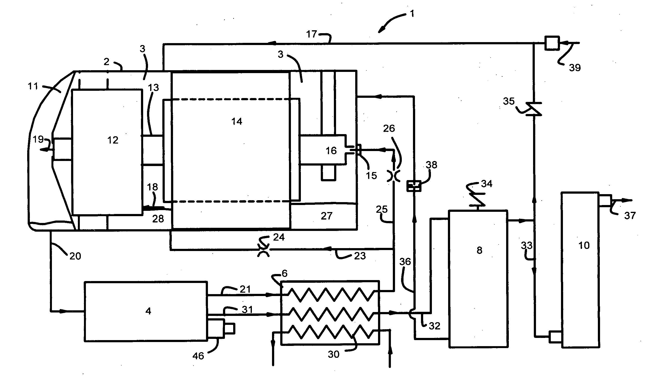
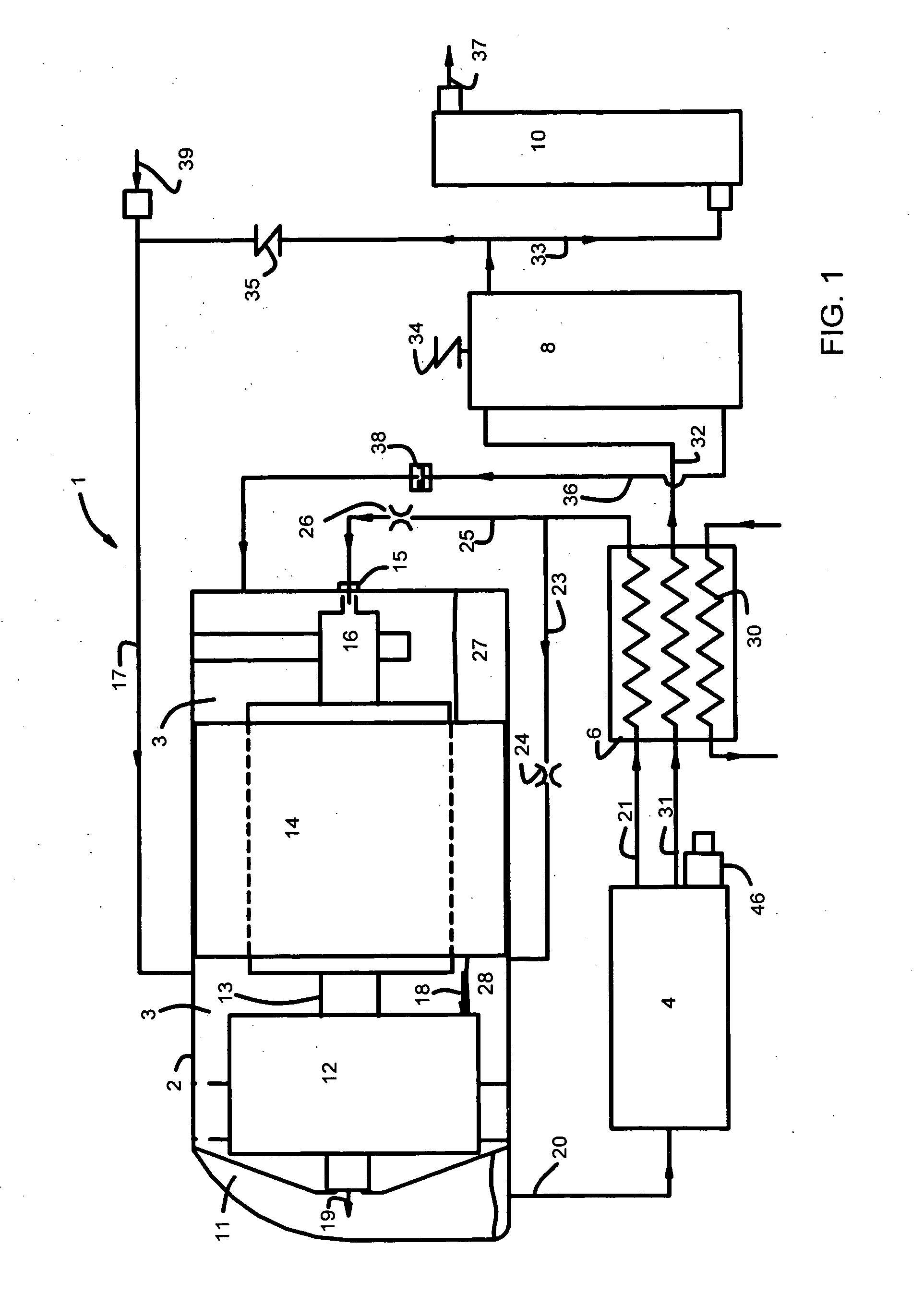
[0051]The bulk oil separator used in the present compressor system, as shown in FIG. 2, has an outside diameter of 10.15 cm (4.0″) and a length of 22.8 cm (9.0″). Oil occupied approximately 50% of the volume. The compressor had a displacement of 98 mL, 338 L / min on 60 Hz power, and an oil circulation rate of about 7 L / min. The gas was helium, and the oil was UCON LBX300™ (LBX Company, LLC). The results obtained for the design and performance of the present horizontal bulk oil separator operating near the limits of test conditions are shown in Table I.

TABLE IInternal volume of bulk oil separator - L1.61.6Test pressures - MPa2.0 / 0.42.1 / 0.8Volume of oil in bulk oil separator - mL500800Gas flow rate - L / min69132Oil flow rate - L / min8.97.1Residence time of gas - s0.950.36Residence time of oil - s3.36.7Oil in gas at outlet, max - mL / hr150150Oil removal efficiency - %99.9799.96Initial rate of oil level change - mL / cm160Rate of oil level change at point where60switch opens - mL / cm

[0052]When...


PUM

PropertyMeasurementUnit
Fractionaaaaaaaaaa
Fractionaaaaaaaaaa
Angleaaaaaaaaaa

Abstract

A high separation efficacy, compact, bulk oil separator oriented horizontally and used with a scroll-type oil-lubricated compressor unit adapted to compressing helium. The horizontal bulk oil separator contains an integral oil reservoir and removes more than 99.9% of the oil from the helium that exits. The bulk oil separator contains successive chambers where oil separates from the gas by impingement.

Description

[0001]This invention relates generally to helium compressor units for use in cryogenic refrigeration systems, operating on the Gifford McMahon (GM) cycle. More particularly, the invention relates to an improved bulk oil separator that is oriented horizontally and is used with a scroll type oil-lubricated compressor unit adapted to compressing helium.BACKGROUND OF THE INVENTION[0002]Helium is typically compressed using air-conditioning type compressors, in which a significant amount of oil flows through the compression chamber with the helium in order to keep it cool. The purpose of oil in GM type cryogenic refrigerator compressors is both for lubrication and to absorb the heat produced in the process of helium compression. It is extremely important that the helium delivered to the expander be virtually oil free. Bulk oil separators are used to ensure removal of such oil injected during the compression process. The bulk oil separator serves as an oil reservoir for the system that is ...

Claims


Application Information

Patent Timeline
IPC IPC(8): F01M11/08
CPCF25B43/02
Inventor DUNN, STEPHEN B.LONGSWORTH, RALPH C.
Owner SHI APD CRYOGENICS
Learn More