
Method for controlling brake chopper, brake chopper and frequency converter

Active Publication Date: 2008-01-17
ABB (SCHWEIZ) AG
View PDF18 Cites 6 Cited by
  • Summary
  • Abstract
  • Description
  • Claims
  • Application Information

AI Technical Summary

Benefits of technology

[0011] An advantage of the method and system of the invention is that the system adjusts in a simple manner to remove power from an intermediate circuit as need arises. The equipment for implementing the method in the system may consist of switch components or modules containing a plural number of switches used in an inverter unit in a prior manner. In addition, the invention may utilize modulators, known per se in frequency converters, for controlling braking power.

Problems solved by technology

A problem with the above brake chopper is that the number of different braking powers to be obtained is fixed, which occasionally leads to an unnecessarily high braking power.

Method used


Image

  • Method for controlling brake chopper, brake chopper and frequency converter
  • Method for controlling brake chopper, brake chopper and frequency converter
  • Method for controlling brake chopper, brake chopper and frequency converter

Examples


Embodiment Construction

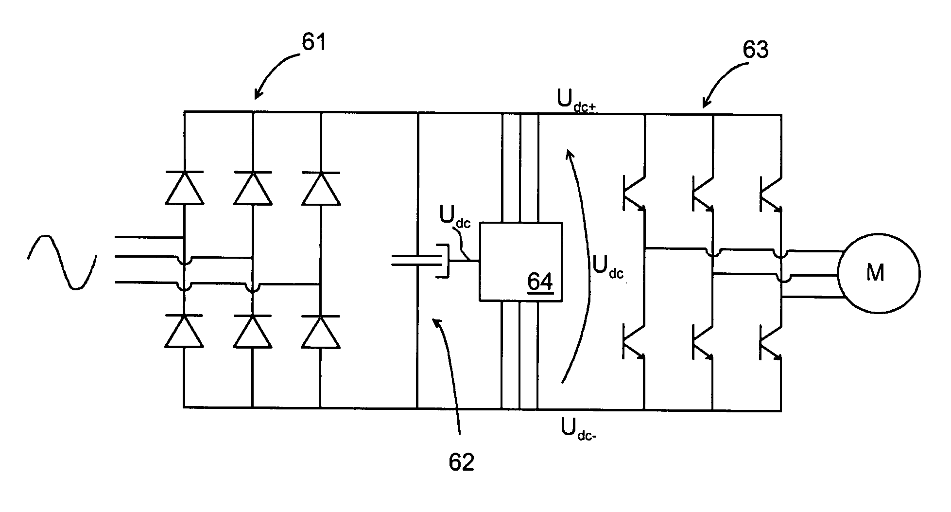
[0023]FIG. 6 is a schematic view of the structure of a frequency converter and a brake chopper associated therewith. The frequency converter consists of a rectifier bridge 61, which in the example of FIG. 6 is a non-controlled diode bridge. The frequency converter is further provided with an intermediate circuit capacitor 62 connected between the positive and negative voltage rails Udc+, Udc− of the frequency converter. The frequency converter also has an inverter portion 63 for generating alternating current from the voltage of the voltage intermediate circuit for a load, which in FIG. 6 is represented by a motor M.

[0024]FIG. 6 shows a brake chopper 64 connected to the intermediate circuit of the frequency converter for reducing the intermediate circuit voltage Udc when the motor functions regeneratively, i.e. generates voltage into the intermediate circuit. In connection with the brake chopper 64 the figure shows how the brake chopper receives information of the intermediate circ...


PUM


Abstract

A method for controlling brake resistors and a brake chopper, the number of brake resistors being two or more and the brake resistors being connected in series with switches to be controlled, the series connection being connected between a positive and a negative rail of a DC voltage intermediate circuit, the method comprising the step of determining a magnitude for a voltage of the DC intermediate circuit; and determining a first voltage limit and a second voltage limit. The method further comprises the steps of switching brake resistors to the intermediate circuit in a periodically alternating manner, each switch being switched during a switching period and the on-period of each switch in a switching period being responsive to the magnitude of the voltage in the DC voltage intermediate circuit when the voltage is above the first predetermined limit and below the second predetermined limit.

Description

BACKGROUND OF THE INVENTION [0001] The invention relates to controlling a brake chopper and in particular to controlling a brake chopper of a DC voltage intermediate circuit of a frequency converter, and to a brake chopper and a frequency converter provided with one. [0002] Brake choppers are used in the DC voltage intermediate circuits of frequency converters in a prior art manner for preventing an increase in the intermediate circuit voltage and for reducing the voltage when a device that normally fed from the frequency converter exceptionally feeds energy back to the intermediate circuit. This kind of situation arises for example when a magnetized motor rotates uncontrolled and thereby functions as a generator feeding power to the DC voltage intermediate circuit. [0003] The situation is the same when a frequency converter is used for active braking of a rotating motor, whereby the power from the braking is transferred to the intermediate circuit. Drives in which braking is used o...

Claims


Application Information

Patent Timeline
IPC IPC(8): H02P3/14
CPCH02P29/024H02P27/06H02P29/0241H02M5/458
Inventor POYHONEN, SIMOHIRVONEN, MIKKOTALJA, MARKKU
Owner ABB (SCHWEIZ) AG
Learn More