Linearized variable-capacitance module and lc resonance circuit using the same

Inactive Publication Date: 2008-01-17
ELECTRONICS & TELECOMM RES INST
View PDF10 Cites 29 Cited by
  • Summary
  • Abstract
  • Description
  • Claims
  • Application Information

AI Technical Summary

Benefits of technology

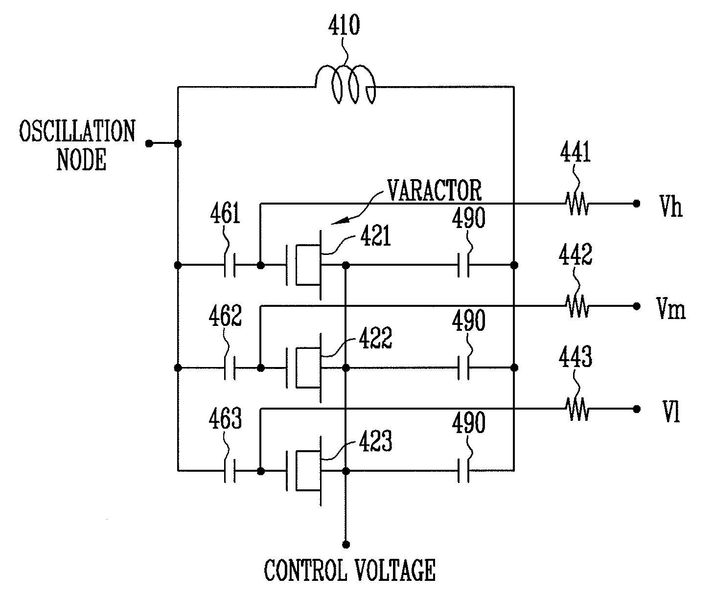
[0011]One aspect of the present invention provides a variable-capacitance module including a plurality of variable-capacitance devices having different linear variation regions on a voltage axis. Herein, the variable-capacitance devices are coupled in common and receive a control voltage at one end while each receiving a different fixed voltage at the other end.
[0012]Another aspect of the present invention provides a single-ended LC resonance circuit including an inductor providing a resonance inductance; and a variable-capacitance module having one end coupled to one end of the inductor and the other end coupled to the other end of the inductor. Herein, the variable-capacitance module includes a plurality of variable-capacitance devices coupled in common and receiving a control voltage at one e

Problems solved by technology

In this case, since the capacitance varies nonlinearly with respect to control voltage as described above, it is impossible to ensure precise control of oscillation

Method used


Image

  • Linearized variable-capacitance module and lc resonance circuit using the same
  • Linearized variable-capacitance module and lc resonance circuit using the same
  • Linearized variable-capacitance module and lc resonance circuit using the same

Examples


Embodiment Construction

[0033]Hereinafter, exemplary embodiments of the present invention will be described in detail. However, the present invention is not limited to the exemplary embodiments disclosed below and can be implemented in various forms. Therefore, the present exemplary embodiments are provided for complete disclosure of the present invention and to fully convey the scope of the present invention to those of ordinary skill in the art.

[0034]FIG. 5 is a conceptual diagram of a linearized variable-capacitance module including n varactors according to an exemplary embodiment of the present invention, and FIG. 6 is a graph of frequency versus control voltage in a voltage-controlled oscillator (VCO) using the linearized variable-capacitance module of FIG. 5.

[0035]As can be seen from the lowermost graph of FIG. 6, one varactor is characterized such that the maximum capacitance Var-n and the minimum capacitance Var-1 are sufficiently within the entire variation range of control voltage. In this case, ...


PUM


Abstract

Provided are a linearized variable-capacitance module for a voltage-controlled oscillator (VCO) and an LC resonance circuit using the same. The VCO is a circuit for outputting a certain frequency in response to an input control signal (voltage or current). The VCO includes an inductor, a variable capacitor (or a varactor), and an active device for compensating for loss of energy caused by the inductor and varactor. The frequency of the VCO is varied by changing inductance or capacitance. In general, the VCO includes a variable-capacitance device (i.e., the varactor) so that the frequency of the VCO may be varies by changing the capacitance via a control voltage. In most cases, the frequency of the VCO varies nonlinearly with respect to the control voltage. The nonlinear variation in the frequency of the VCO results in a great variation in a VCO gain within a certain control voltage range. When a phase locked loop (PLL) includes the VCO, the variation in the VCO gain leads to a variation in the entire loop gain, thus causing a variation in output phase noise. To solve this problem, a varactor designed to have a capacitance that varies linearly with a control voltage is provided so that a VCO gain can be held constant. The variable-capacitance module includes a plurality of variable-capacitance devices with respectively different linear variation regions on an application voltage axis. Also, the variable-capacitance devices are coupled in common and receive a control voltage at one end while each receiving a different fixed voltage at the other end.

Description

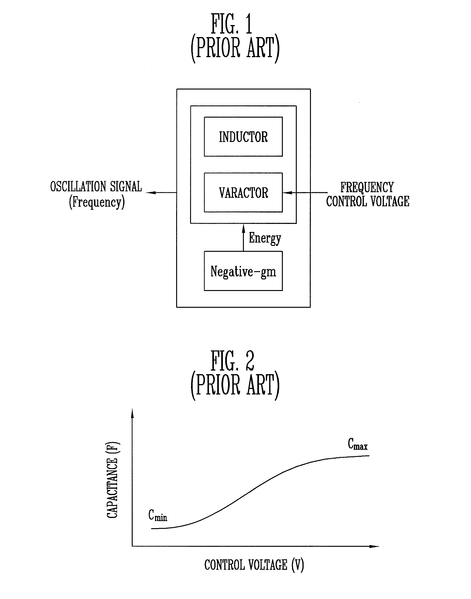
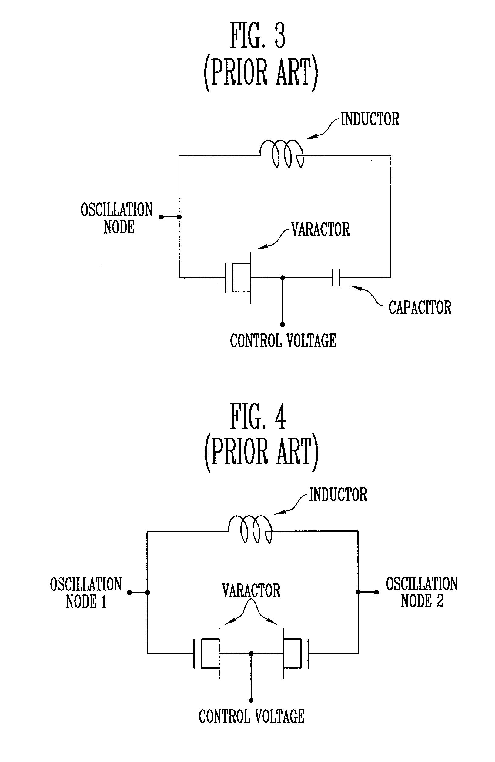
CROSS-REFERENCE TO RELATED APPLICATION[0001]This application claims priority to and the benefit of Korean Patent Application No. 2006-0066409, filed Jul. 14, 2006, the disclosure of which is incorporated herein by reference in its entirety.BACKGROUND[0002]1. Field of the Invention[0003]The present invention relates to a variable capacitor (hereinafter, varactor) applicable to a voltage-controlled oscillator (VCO), which generates a signal at a frequency that varies linearly with a control voltage.[0004]2. Discussion of Related Art[0005]FIG. 1 is a block diagram of a conventional voltage-controlled oscillator (VCO). The VCO is a circuit for generating an output signal at a specific frequency in response to a control signal. The VCO includes an inductor-capacitor (LC) resonance circuit, which is comprised of an inductor and a capacitor, and an active device for compensating for undesirable energy loss caused by the LC resonance circuit. In the LC resonance circuit, the frequency is va...

Claims


Application Information

Patent Timeline
IPC IPC(8): H03B5/08
CPCH03B2200/0048H03B2200/005H03J3/185H03J7/045H03J2200/10H03B5/1293H03L7/099H03L2207/06H03B5/1265H03B5/1253H03J2200/36H03B5/18H03H7/01H03H5/02
Inventor HAN, SEON HOKIM, CHEON SOO
Owner ELECTRONICS & TELECOMM RES INST
Why Eureka
Try Eureka