
Variable flow valve

a flow valve and variable technology, applied in the direction of valve operating means/releasing devices, functional valve types, containers, etc., can solve the problems of increased gas volume circulating the breather circuit, increased adsorption of fuel to the canister, and increased adsorption of gas to the canister, so as to improve stability and improve the stability of movement. , the effect of improving the accuracy

Inactive Publication Date: 2008-01-24
TOYODA GOSEI CO LTD
View PDF5 Cites 8 Cited by
  • Summary
  • Abstract
  • Description
  • Claims
  • Application Information

AI Technical Summary

Benefits of technology

[0021]The present invention has been developed in view of the aforementioned circumstances. It is therefore an object of the present invention to provide a small-sized variable flow valve, which can reduce the ventilation pressure loss, and which can make fuel vapors flow in a much greater flow volume.

Problems solved by technology

However, when a fuel sucks in fresh air through a fuel supply opening in a large volume in supplying fuel to an automotive fuel tank, fuel vaporizes facilitatively in the fuel tank.
Consequently, there might arise a problem that the adsorption amount of gases to the canister has increased.
However, when enlarging the opening of the orifice, the breather gas volume circulating the breather circuit has increased even in low-rate fuel supply.
Consequently, vapor leakage might occur through the fuel supply opening.
However, when diminishing the opening of the orifice, the volume difference has increased between the sucked-in air volume and the breather gas volume in fast-rate fuel supply.
Under such contradicting circumstances, there might arise a problem that the conventional breather circuit cannot cope with the required increment / decrement of breather gas depending on the increment / decrement of fuel-supply rate.
However, using the means for making an opening area variable, means which is disclosed in Japanese Unexamined Patent Publication (KOKAI) Gazette No. 8-216,707, results in the following problem that the apparatus is susceptible to the limited on-board space.
If such is the case, the size of the case (60) has enlarged so that the resulting apparatus suffers from the problem of limited on-board space.
Consequently, the conventional variable flow valve might have such a drawback that it has exhibited a large ventilation pressure loss.
However, these conventional valve assemblies might suffer from the following drawback.
As a result, the conventional valve assemblies have been large-sized so that they are disadvantageous in view of on-board space.

Method used


Image

  • Variable flow valve
  • Variable flow valve
  • Variable flow valve

Examples


examples

[0081]The present variable flow valve will be hereinafter described in more detail with reference to specific examples.

example no.1

Example No. 1

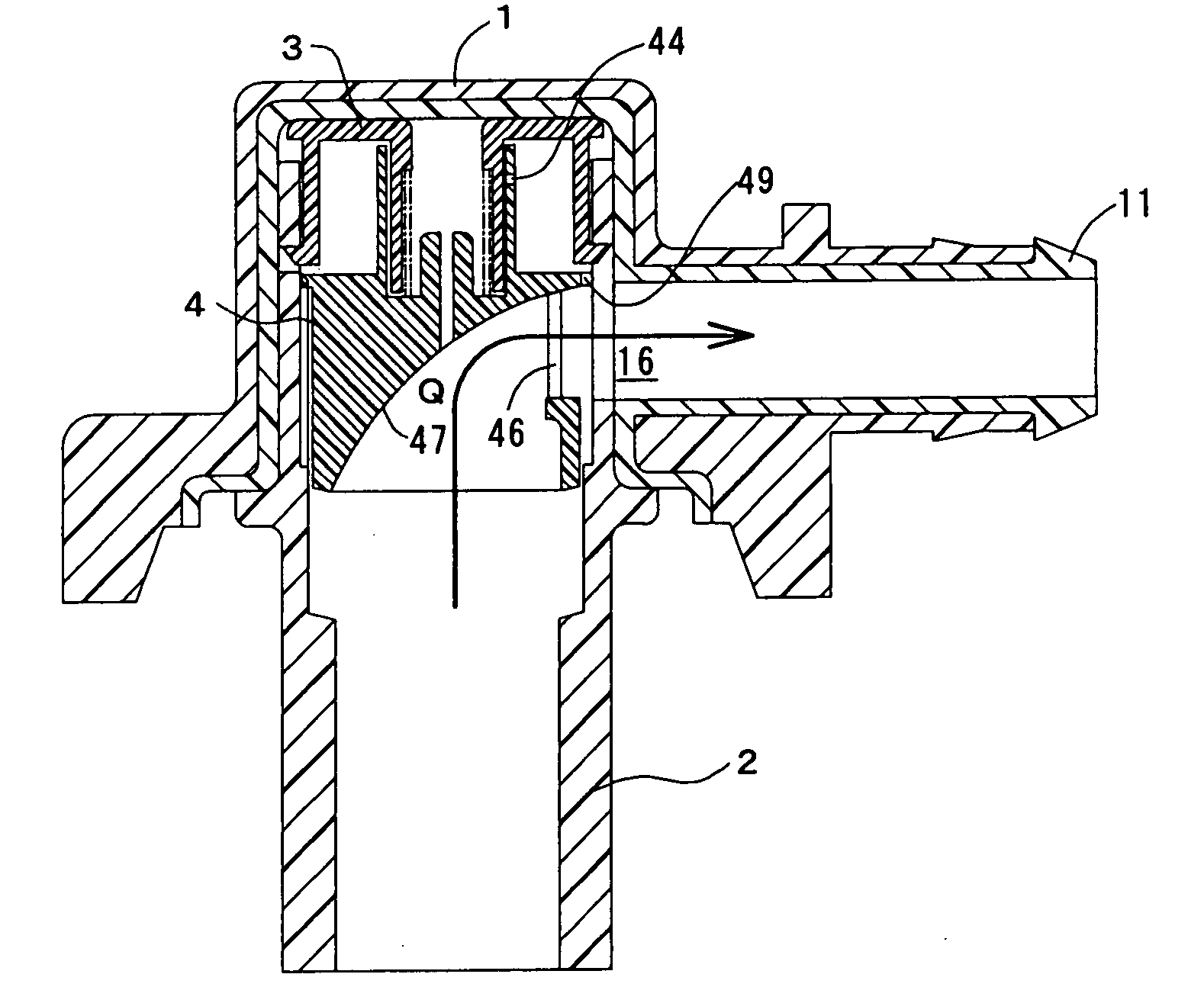
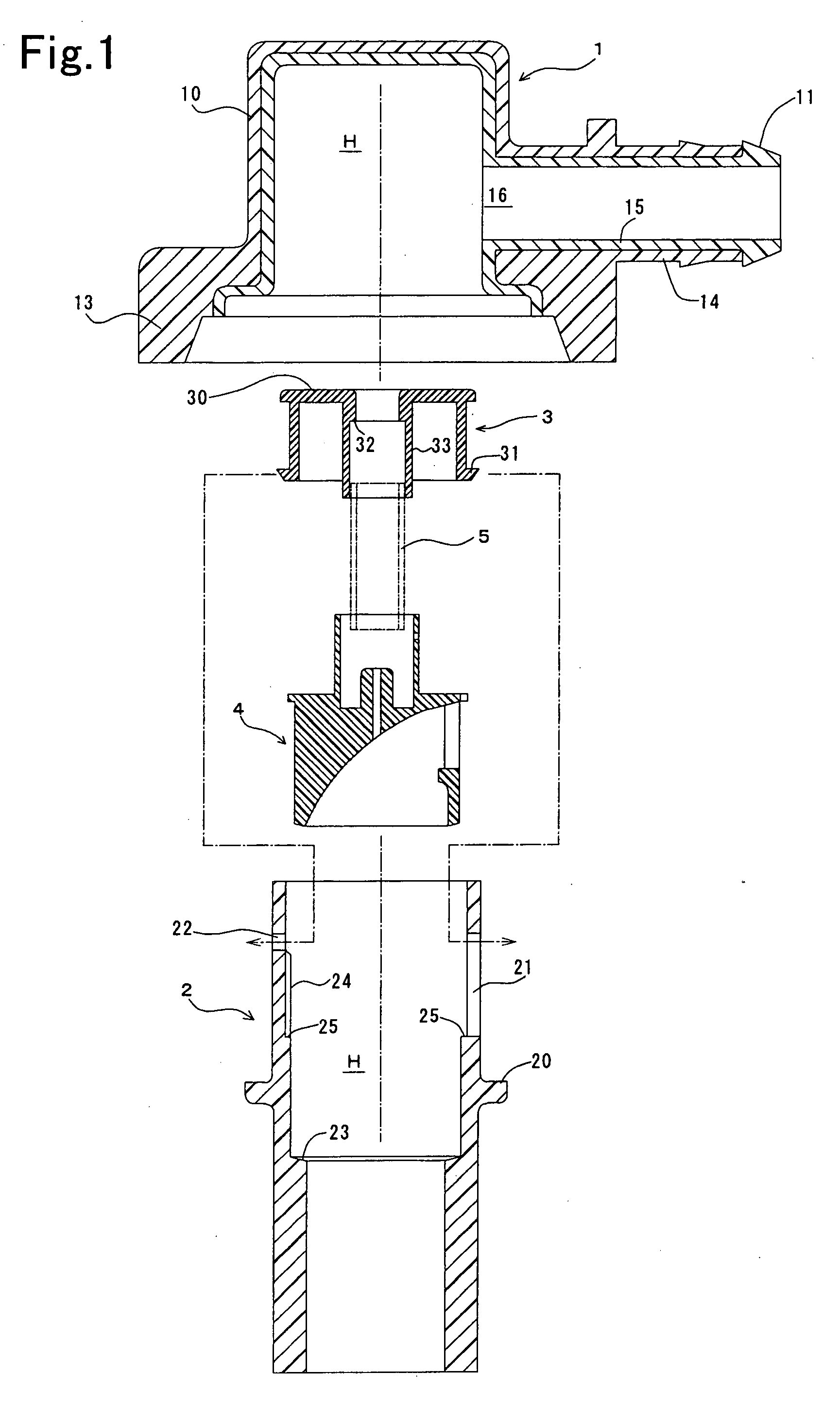
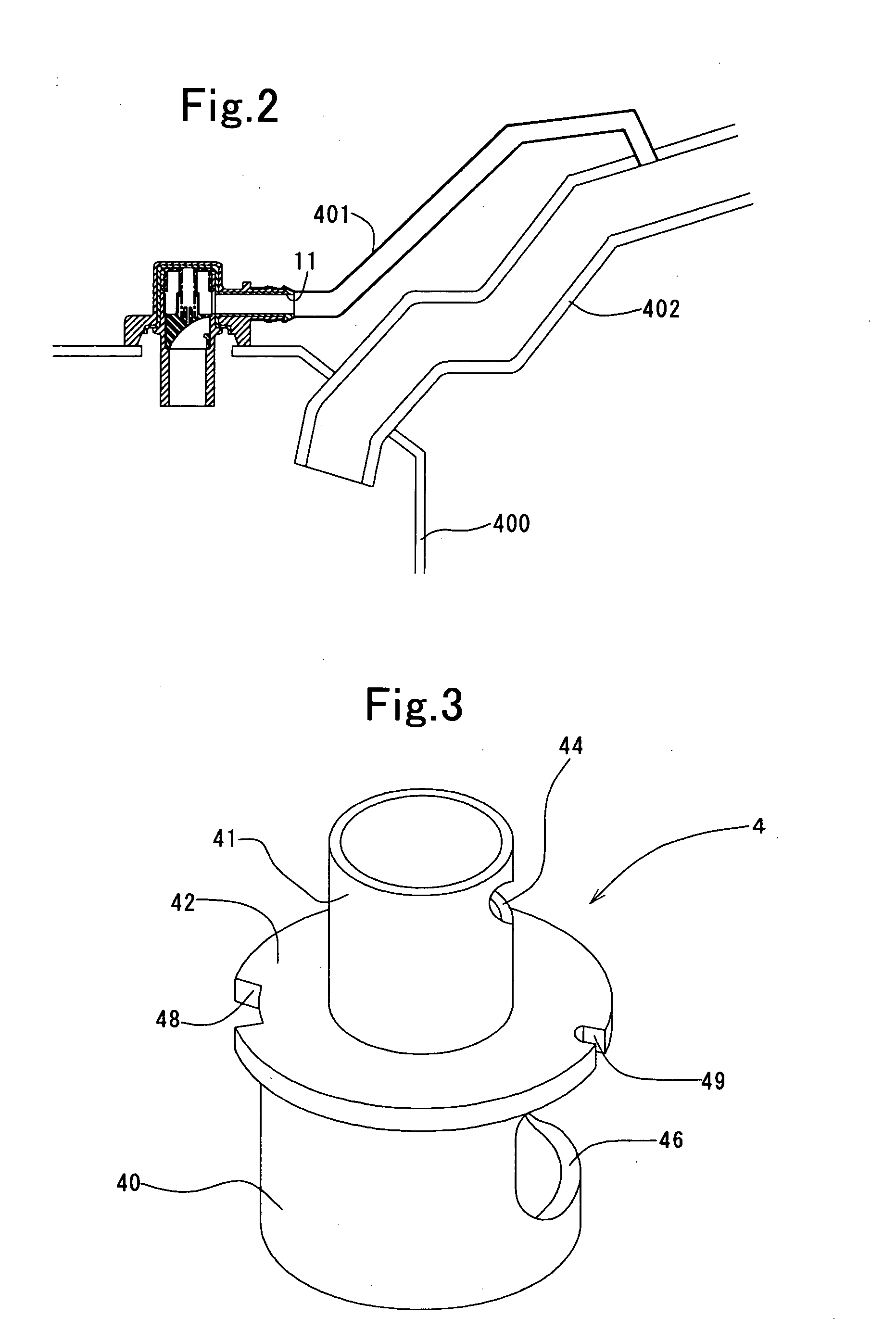
[0082]FIG. 1 shows a cross-sectional view for each of the component parts of a variable flow valve according to Example No. 1 of the present invention. FIGS. 5 and 6 show cross-sectional views of the variable flow control valve according to Example No. 1 after being assembled. As illustrated in FIG. 2, the variable flow valve according to Example No. 1 is fixed to a top of a fuel tank 400 by welding. The variable flow valve according to Example No. 1 comprises a nipple 11, which is fitted into a breather tube 401. The breather tube 401 is connected with a part of an inlet pipe 402, part which is positioned adjacent to a fuel supply opposite opening of the inlet pipe 402.

[0083]As shown in FIG. 1, the variable flow valve according to Example No. 1 of the present invention comprises a cover 1, a cylinder-shaped member 2, a seat plate 3, a valve element 4, and a spring 5. The cover 1 is manufactured by two-color molding. Note that the cylinder-shaped member 2 is fixed to th...

example no.2

Example No. 2

[0102]Except that the valve element 4 is formed differently from that of the variable flow valve according to Example No. 1 of the present invention, a variable flow valve according to Example No. 2 comprises the same component parts as those of the variable flow valve according to Example No. 1. Specifically, in the variable flow valve according to Example No. 2, the valve element 4's cylinder 40 is provided with a slit-shaped opening 46′, as illustrated in FIG. 7, instead of the through-holed opening 46. Moreover, a part of the valve element 4's separator wall 42 is provided with a through-holed communicating portion 49′, as shown in the drawing, instead of the cut-off communicating portion 49.

[0103]In the thus configured valve element 4, although the cylinder-shaped portion 40's lower end is cut off partially by the slit-shaped opening 46′, most of the entire circumference is left as it is. As a result, the valve element 4 ascends while the cylinder-shaped portion 40...


PUM


Abstract

A variable flow valve includes a housing, a valve element, an urging member, a first valve, a second valve, and a guide flow passage. The housing has an inlet opening, and an outlet opening. The first valve and second valve are formed between the valve element and the housing. The valve element has a separator wall. The separator wall separates the inlet opening and the outlet opening, and makes the second valve together with the housing. The guide flow passage is disposed on an inlet-opening side of the separator wall, and connects the inlet opening with the outlet opening when the separator wall moves to open the communication between the inlet opening and the outlet opening. The variable flow valve can make fluids flow without generating any turbulent flow, and can cope with the increment / decrement of required breather-gas flow volume more accurately.

Description

BACKGROUND OF THE INVENTION[0001]1. Field of the Invention[0002]The present invention relates to a variable flow valve, which is used in breather circuits for fuel tanks.[0003]2. Description of the Related Art[0004]In the vicinity of automobile fuel tanks, a vaporized-fuel circulating system, a so-called evaporator circuit, is disposed. The evaporator circuit leads vaporized fuels from fuel tanks to external canisters. The vaporized fuels are then adsorbed to activated carbon, and are stored temporarily therein. Thus, the evaporator circuit inhibits the vaporized fuels from being emitted into the outside air. The canisters are connected with engines, and engines exert an inlet negative pressure to release the adsorbed vaporized fuels from activated carbon to remix them into an air-fuel mixture. Accordingly, the adsorbed vaporized fuels are reused as fuels.[0005]However, when a fuel sucks in fresh air through a fuel supply opening in a large volume in supplying fuel to an automotive ...

Claims


Application Information

Patent Timeline
IPC IPC(8): F16K24/00
CPCF16K31/1635Y10T137/0874Y10T137/3099Y10T137/7771Y10T137/7845
Inventor KANEKO, KENICHIRO
Owner TOYODA GOSEI CO LTD
Learn More