Sheet peeling apparatus and peeling method

a peeling apparatus and peeling technology, applied in the direction of door/window protective devices, instruments, structural/machine measurement, etc., can solve the problems of large peeling force, failure of peeling, and large force required for peeling off, so as to reduce peeling force, reduce peeling width, and reduce peeling force

Active Publication Date: 2008-01-24
LINTEC CORP
View PDF4 Cites 28 Cited by
  • Summary
  • Abstract
  • Description
  • Claims
  • Application Information

AI Technical Summary

Benefits of technology

[0027]According to the present invention, since a swing mechanism is provided so that the support means and the peeling head perform a zigzag movement when moving relatively each other, the peeling operation is carried out alternately within a plane with respect to the relative movement direction, whereby the peeling operation can be carried out with a small peeling width. Therefore, the peeling width is restricted from becoming extremely large; and owing to this, the peeling force is restrained to effectively prevent the peeling tape from slipping off or being broken, or the sheet itself stuck on the front surface from being torn off.
[0028]Also, by arranging the swing mechanism between the table and the base, such a structure is obtained that the swing mechanism is incorporated into the moving means.

Problems solved by technology

However, in the sheet peeling method using the peeling apparatus disclosed in the patent document 1, as the peeling of the protective sheet progresses, larger force is required to peel off the protective sheet from the wafer.
As a result, as the

Method used


Image

  • Sheet peeling apparatus and peeling method
  • Sheet peeling apparatus and peeling method
  • Sheet peeling apparatus and peeling method

Examples


Embodiment Construction

[0054]Now, referring to the drawings, preferred embodiments of the present invention will be described below.

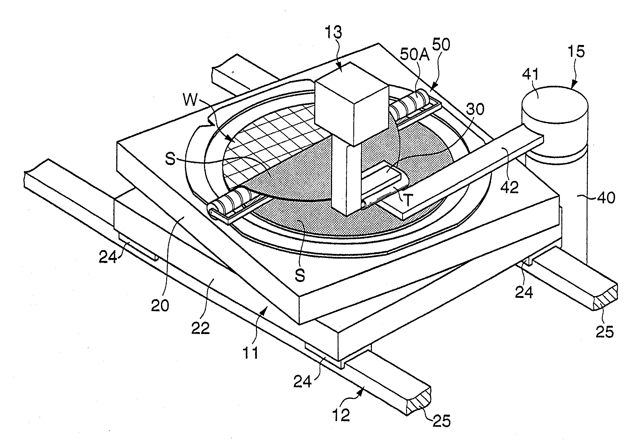
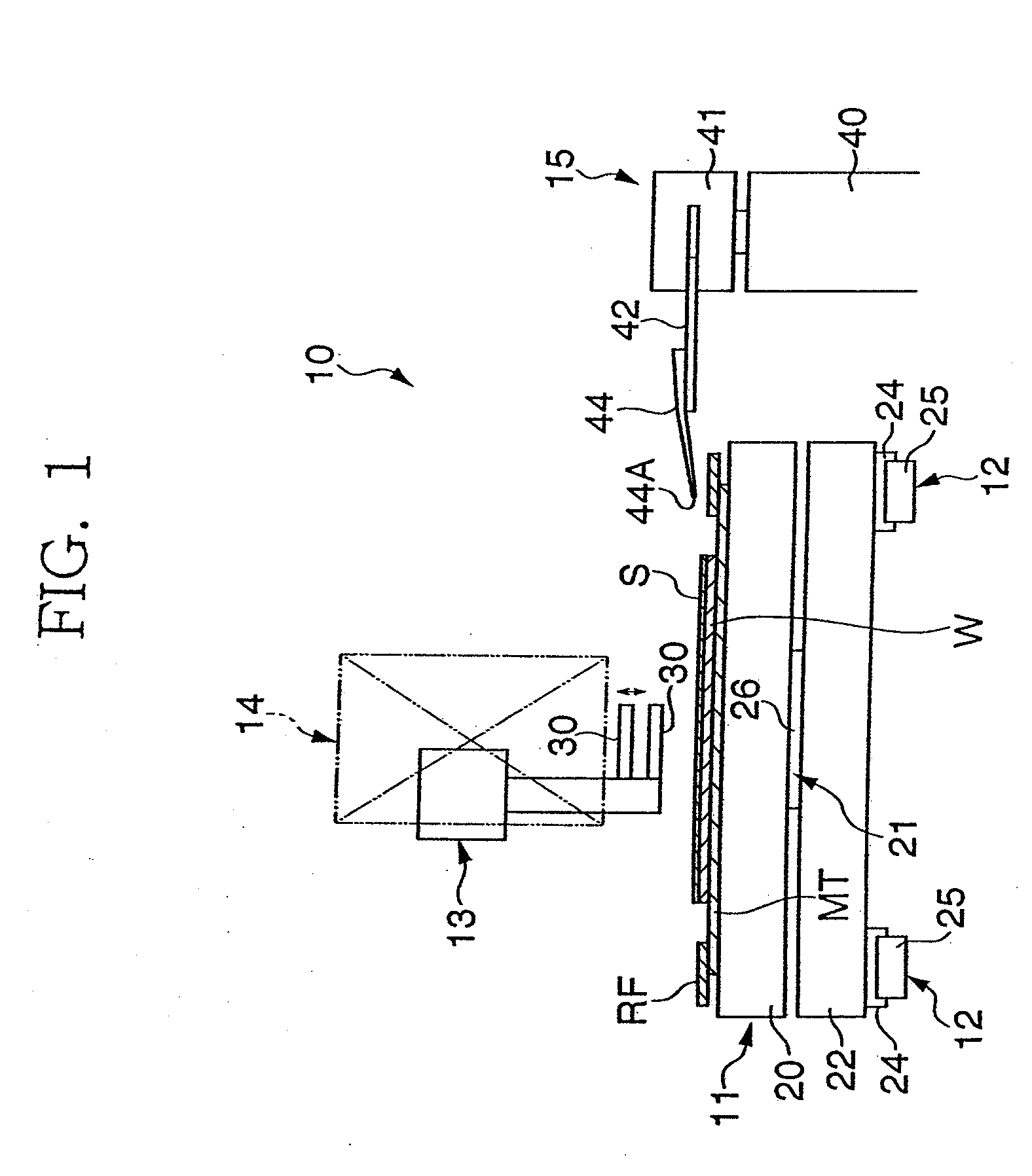
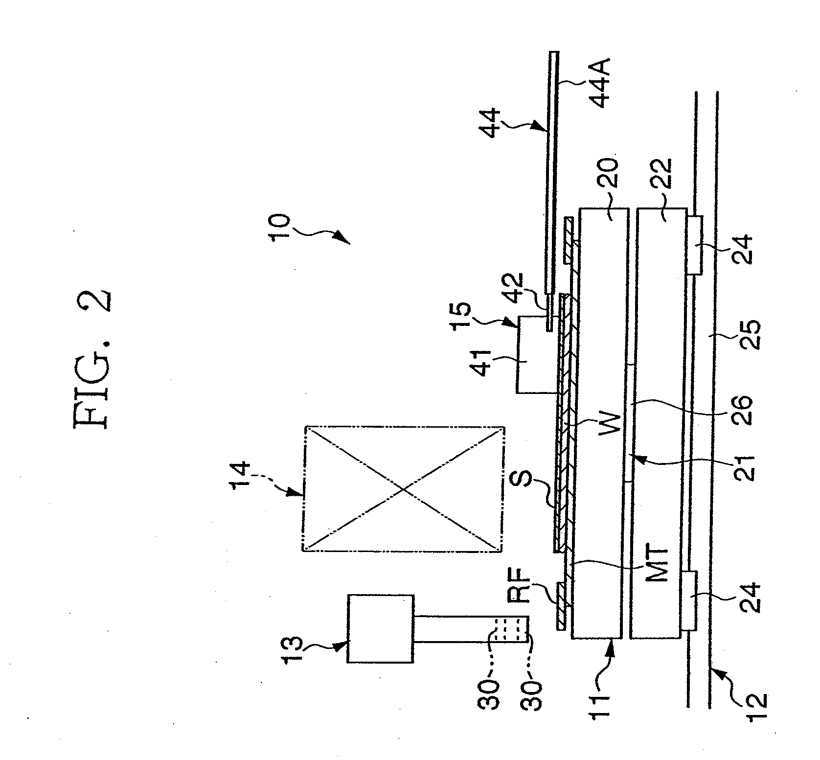
[0055]FIG. 1 shows a schematic front view of a sheet peeling apparatus according to an embodiment of the present invention, and FIG. 2 shows a schematic right-side view thereof. Referring to these figures, a sheet peeling apparatus 10 comprises a support means 11 that supports a wafer W as an adherend stuck with an adhesive sheet S (hereinafter, referred to as “sheet S”) on a front surface (circuit surface) thereof at the upper surface side in the figures, a moving means 12 that supports the support means 11 in a movable manner, a peeling head 13 that sticks a peeling tape T (refer to FIG. 3) to a peripheral portion of the sheet S and peels off the sheet S from the wafer W, a tape supply unit 14 that has a function to feed out the peeling tape T at intervals of a predetermined length and to melt a part of the peeling tape T to bond the same to the sheet S by heat, and a peeli...


PUM

PropertyMeasurementUnit
Forceaaaaaaaaaa
Angleaaaaaaaaaa

Abstract

A sheet S is stuck on the front surface of a wafer W, and the wafer W is supported on a table 20. A peeling tape T is stuck onto a peripheral portion of the sheet S and the peeling tape T is held by a peeling head 13. The peeling head 13 and the table 20 perform a relative movement along guide rails 25, the table 20 rotates a predetermined angle in clockwise and counterclockwise directions alternately via a swing mechanism 21 thereby peeling off the sheet S from the wafer W accompanying a zigzag movement.

Description

BACKGROUND OF THE INVENTION[0001]1. Field of the Invention[0002]The present invention relates to a sheet peeling apparatus and a peeling method, in particular, to a sheet peeling apparatus and a peeling method capable of, when peeling off a protective sheet or the like stuck on an adherend such as a semiconductor wafer, performing the peeling while controlling to reduce a peeling force.[0003]2. Related Art[0004]Conventionally, a semiconductor wafer (hereinafter, simply referred to as “wafer”) is stuck with a protective sheet for protecting a circuit surface thereof. The protective sheet is peeled off via a sheet peeling apparatus, for example, after a back grinding processing is carried out on the wafer.[0005]As a sheet peeling method mentioned above, there is known, for example, a method using a sheet peeling apparatus disclosed in a patent document 1. The apparatus is arranged to stick a peeling tape to a protective sheet and wind the peeling tape with a roller thereby peeling off...

Claims


Application Information

Patent Timeline
IPC IPC(8): B32B38/10
CPCH01L21/67132Y10T156/1168Y10T156/19Y10T156/1179Y10T156/1978H01L21/02
Inventor YOSHIOKA, TAKAHISASUGISHITA, YOSHIAKI
Owner LINTEC CORP
Why Eureka
Try Eureka