Low supply voltage band-gap reference circuit and negative temperature coefficient current generation unit thereof and method for supplying band-gap reference current

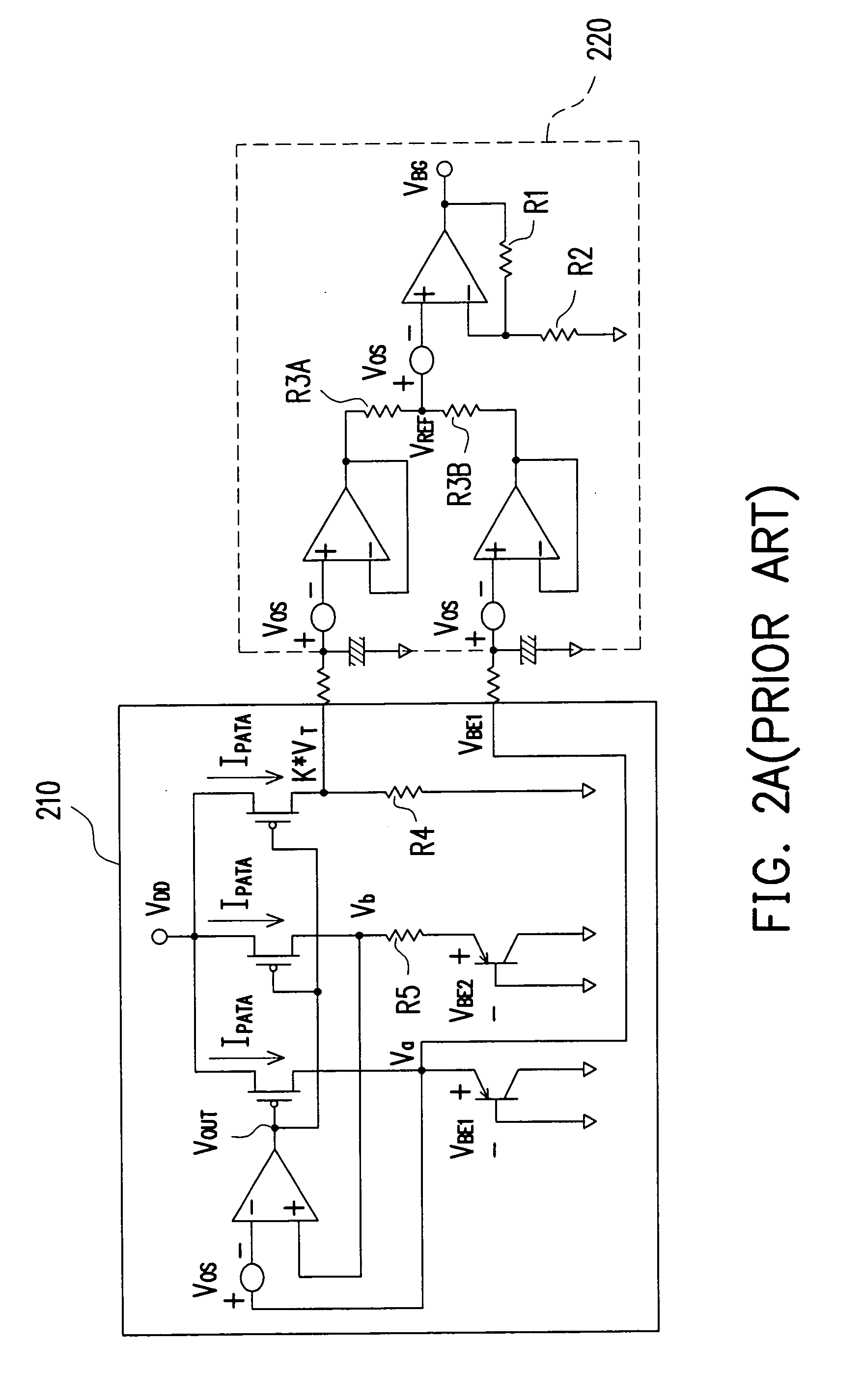
a low-voltage band-gap reference circuit and negative temperature coefficient current technology, applied in pulse generators, instruments, pulse techniques, etc., can solve the problems of increasing chip area and chip cost, significantly increasing the complexity of the band-gap reference circuit in fig. 2a, and achieving the effect of reducing circuit area and cos

Inactive Publication Date: 2008-01-24
FARADAY TECH CORP
View PDF12 Cites 66 Cited by
  • Summary
  • Abstract
  • Description
  • Claims
  • Application Information

AI Technical Summary

Benefits of technology

[0008]An object of the present invention is to provide a low supply voltage band-gap reference circuit, us

Problems solved by technology

Since more than three operational amplifiers and resistors R1, R2, R3A, and R3B of high resistance are required in the conventional art, the complexity of the band-gap reference c

Method used


Image

  • Low supply voltage band-gap reference circuit and negative temperature coefficient current generation unit thereof and method for supplying band-gap reference current
  • Low supply voltage band-gap reference circuit and negative temperature coefficient current generation unit thereof and method for supplying band-gap reference current
  • Low supply voltage band-gap reference circuit and negative temperature coefficient current generation unit thereof and method for supplying band-gap reference current

Examples


Embodiment Construction

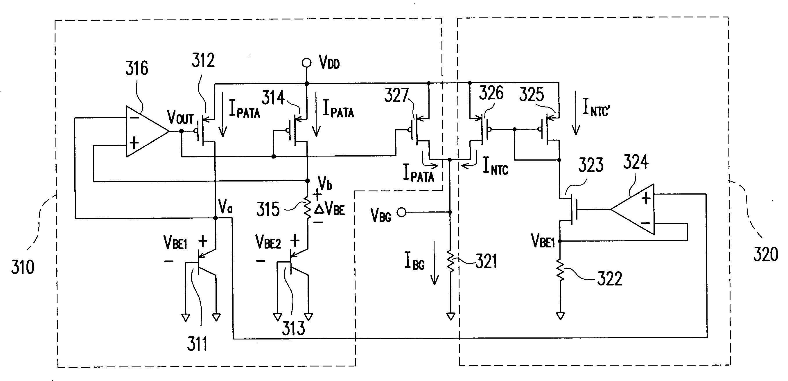
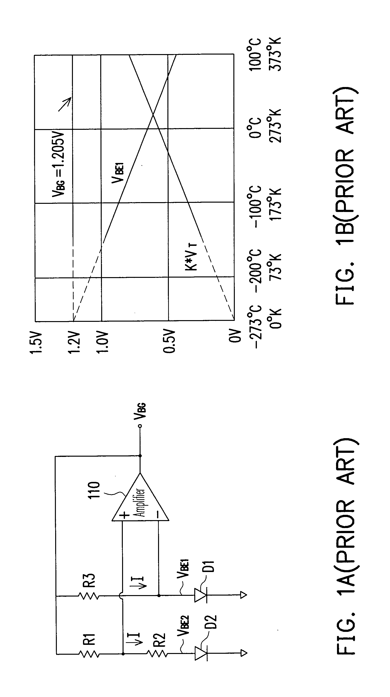
[0025]In many ultra-large integrated circuits, a band-gap reference circuit is generally built-in for generating the source reference voltage. Currently, considering the case of low voltage and low power, the band-gap reference circuit requires a low band-gap voltage with a voltage lower than 1.205 V. FIG. 3A shows an embodiment of a low supply voltage band-gap reference circuit according to the present invention. Referring to FIG. 3A, this band-gap reference circuit comprises a positive temperature coefficient current generation unit 310 and a negative temperature coefficient current generation unit 320. In the positive temperature coefficient current generation unit 310, a first operational amplifier 316 outputs a voltage Vout for adjusting the P-type transistors 312 and 314, such that Va=Vb, thereby generating a positive coefficient current IPTAT with a positive temperature coefficient according to the voltage across the resistor 315. The negative temperature coefficient current ...


PUM


Abstract

A low supply voltage band-gap reference circuit is provided, which includes a positive temperature coefficient current generation unit and a negative temperature coefficient current generation unit, and it is implemented by way of current summing. Through the current-mode temperature compensation technique, the present invention is able to reduce the voltage headroom and the number of operational amplifiers required by the conventional voltage-summing method, as well as the influence to the output voltage due to the offset voltage, thereby providing a stable and low voltage band-gap reference voltage level. In addition, by reducing the number of operational amplifiers and resistors of high resistance, the circuit area is reduced, and chip cost is saved.

Description

BACKGROUND OF THE INVENTION[0001]1. Field of Invention[0002]The present invention relates to a band-gap reference circuit, and more particularly, to a low supply voltage band-gap reference circuit.[0003]2. Description of Related Art[0004]Generally, in many ultra-large integrated circuit (IC) systems, basic and essential semiconductor band-gap circuits are built-in. Responsible for generating source reference current (or voltage), the band-gap circuit determines the accuracy of the whole system.[0005]FIG. 1A is a circuit diagram of a conventional band-gap reference circuit. FIG. 1B shows a relationship diagram between the output voltage and temperature of the conventional band-gap reference circuit shown in FIG. 1A. Referring to both FIG. 1A and FIG. 1B, if the currents passing through diodes D1 and D2 are both I, the proportion between element areas of the diodes D1 and D2 is 1:n, and the resistance R1=R3, the output voltage of the operational amplifier110VBG=VBE1+R1R2(VBE1-VBE2)=VB...

Claims


Application Information

Patent Timeline
IPC IPC(8): G05F3/16
CPCG05F3/30
Inventor CHANG, KUEN-SHANUANG, UEI-SHANCHEN, MEI-SHOWHONG, CHIA-MING
Owner FARADAY TECH CORP
Why Eureka
Try Eureka