Surface-Mount Antenna and Radio Communication Apparatus Including the Same

Inactive Publication Date: 2008-01-24
MURATA MFG CO LTD
View PDF6 Cites 6 Cited by
  • Summary
  • Abstract
  • Description
  • Claims
  • Application Information

AI Technical Summary

Benefits of technology

[0013] According to the above-mentioned embodiment of the present invention, the radiation electrode includes a portion whose width is increased as it goes from the feeding portion toward the open end. This radiation electrode can serve as a monopole antenna. The radiation electrode can exhibit a horizontal-plane non-directional characteristic depending on the shape of the radiation electrode, moreover easily achieving a wider frequency band and improved VSWR. In this embodiment of the present invention, the radiation electrode is entirely formed on a surface of the base member formed of a dielectric member or a magnetic member. Accordingly, since the whole area of the radiation electrode is influenced by the base member, there is a wavelength shortening effect in accordance with the dielectric constant of the base member. Thus, it is easy to reduce the size of the radiation electrode (i.e., to miniaturize the surface-mount antenna).
[0014] The radiation electrode is formed on the surface of the base member. Accordingly, by simply disposing the base member provided with the radiation electrode on, for example, the circuit board of the radio communication apparatus, the surface-mount antenna can be integrated into the radio communication apparatus easily and quickly. For example, by fixing the base member of the surface-mount antenna on the circuit board of the radio communication apparatus by soldering, the surface-mount antenna can be fixed (surface-mounted) on the circuit board of the communication apparatus simultaneously with the surface-mounting step of fixing electronic components on the circuit board by soldering. This eliminates the need to provide a step of integrating the surface-mount antenna into the circuit board separately from the step of mounting electronic components on the circuit board. Thus, the manufacturing process for the radio communication apparatus can be simplified.
[0015] With the embodiments of the present invention, it becomes easy to increase the frequency bandwidth, to improve VSWR, and to reduce the size of the surface-mount antenna. The operation for integrating the surface-mount antenna into the radio communication apparatus can also be facilitated.
[0017] Additionally, as the frequency increases, the capacitance between the feeding portion of the radiation electrode and the ground produces a greater influence on the resonance operation (for example, the resonant frequency) of the radiation electrode. Thus, if the capacitance between the feeding portion of the radiation electrode and the ground is set to be variable, the resonant frequency of the higher modes, which are higher than the resonant frequency of the fundamental mode, can be changed more sharply than the resonant frequency of the fundamental mode, which is the lowest frequency among a plurality of resonant modes of the radiation electrode. In other words, by varying the capacitance between the feeding portion of the radiation electrode and the ground generated by the feeding electrode and the ground electrode, the resonant frequency of the higher modes can be changed sharply while suppressing a change in the resonant frequency of the fundamental mode of the radiation electrode.
[0018] In the present invention, the spacing between the ground electrode and the feeding electrode is preferably smaller than the width of the feeding electrode. With this configuration, the capacitance between the feeding portion of the radiation electrode and the ground becomes larger, as compared with the case where the spacing between the ground electrode and the feeding electrode is larger than the width of the feeding electrode. Because of this large capacitance between the feeding portion of the radiation electrode and the ground, the resonant frequency of the higher modes of the radiation electrode can be changed to get closer to the resonant frequency of the fundamental mode while suppressing the change of the resonant frequency of the fundamental mode of the radiation electrode. Thus, the frequency band of the higher modes can be partially overlapped with the frequency band of the fundamental mode. That is, the coupling frequency band between the frequency band of the fundamental mode and the frequency band of the higher modes can be formed so that the frequency bandwidth can be increased.

Problems solved by technology

It is thus difficult to miniaturize the antenna 30.
This makes the process of integrating the radiation electrode 32 into a radio communication apparatus troublesome, and the manufacturing cost becomes high.

Method used


Image

  • Surface-Mount Antenna and Radio Communication Apparatus Including the Same
  • Surface-Mount Antenna and Radio Communication Apparatus Including the Same
  • Surface-Mount Antenna and Radio Communication Apparatus Including the Same

Examples


first embodiment

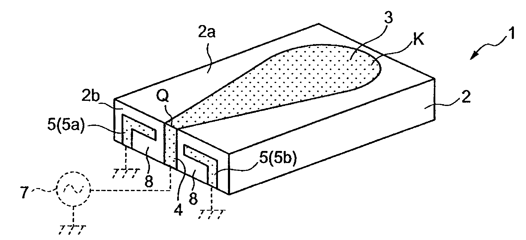
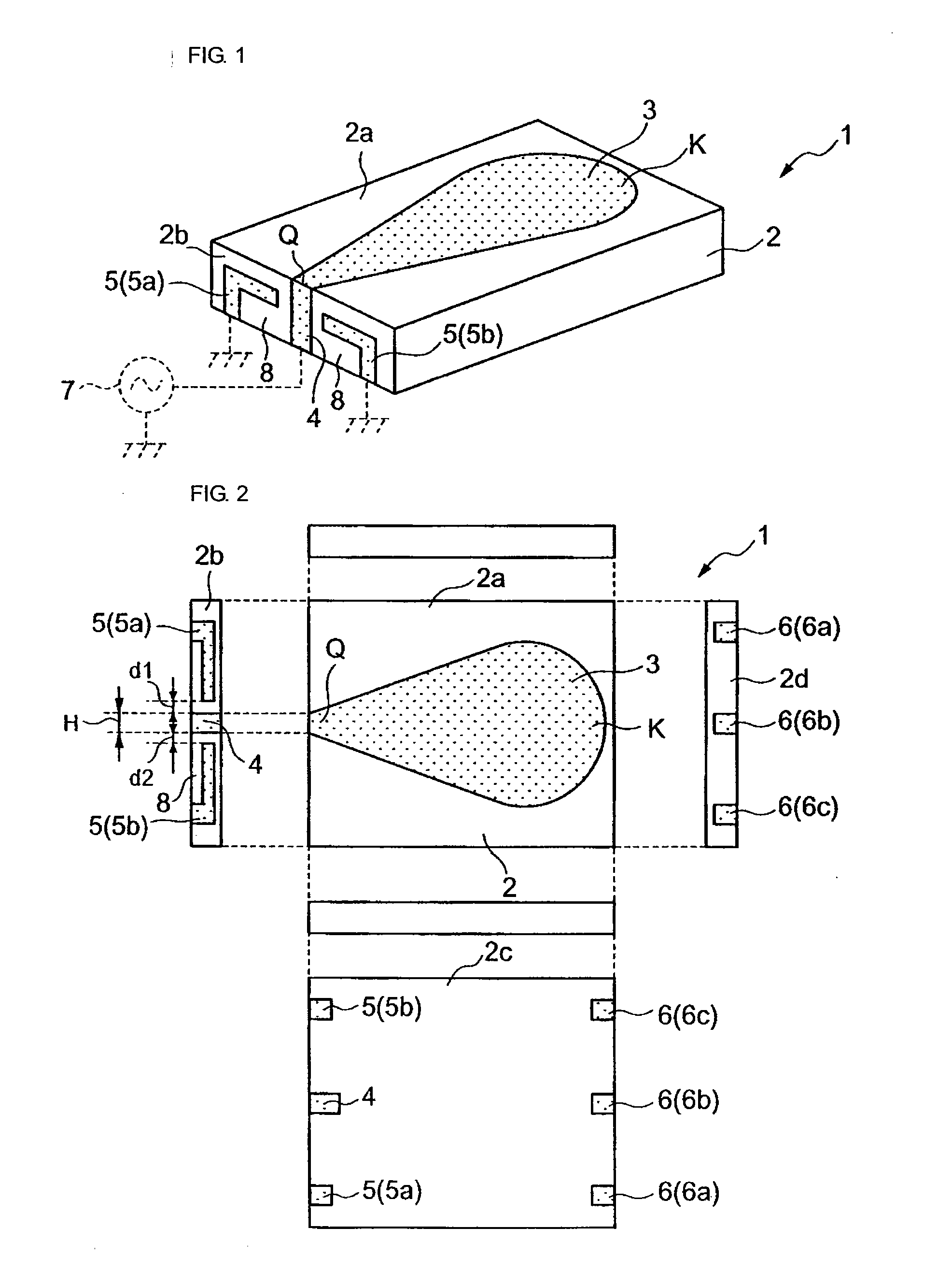
[0085] The ground electrodes 5 (5a, 5b) are disposed on the lateral surface 2b, on opposite sides of the feeding electrode 4 with a spacing therebetween. The ground electrodes 5 (5a, 5b) are grounded. The ground electrodes 5 (5a, 5b) are extended from the lateral surface 2b to the edge of the bottom surface 2c of the dielectric base member 2. In the first embodiment, the spacing d1 between the ground electrode 5a and the feeding electrode 4 and the spacing d2 between the ground electrode 5b and the feeding electrode 4 are smaller than the width H of the feeding electrode 4.

[0086] In the first embodiment, the ground electrodes 5 (5a, 5b) are provided with notches 8 defined at positions near the feeding electrode 4, extending from the bottom edge of the lateral surface 2b adjacent to the bottom surface 2c of the dielectric base member, to a level defined below the top edge of the lateral surface 2b and below the ground electrodes 5a, 5b.

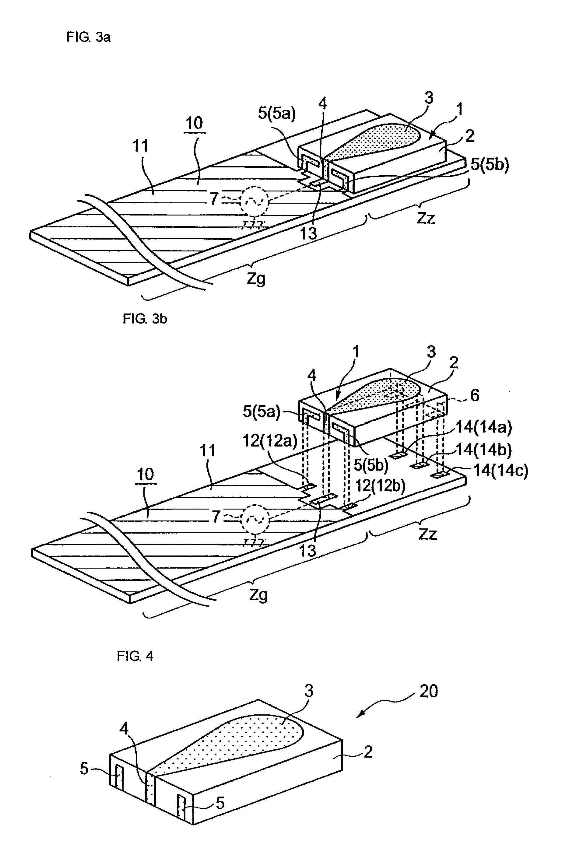
[0087] When surface-mounting the surface-mount ...

second embodiment

[0105] The present inventor further conducted the following experiment. In that experiment, the reflection characteristics of the surface-mount antenna 1 having the configuration of the second embodiment were simulated by variously changing the width H of the feeding electrode 4 and the spacing d1 and the spacing d2 between the feeding electrode 4 and the ground electrodes 5 in the following manner under the condition that the surface-mount antenna 1 was mounted on the circuit board 10, as shown in FIG. 8a. More specifically, in that experiment, in the surface-mount antenna 1, such as that shown in FIG. 6, the width H of the feeding electrode 4 was changed by 0.1 mm in a range from 0.3 mm to 2.0 mm including electrode widths that are usable in a practical sense. When the width H of the feeding electrode 4 ranges from 0.4 mm to 1.7 mm, the spacing d1 and the spacing d2 between the feeding electrode 4 and the ground electrodes 5 are set to be 0.3 mm, and are also changed to the value ...


PUM


Abstract

A surface-mount antenna, in which a radiation electrode to be connected to a radio-communication high-frequency circuit to operate as an antenna is formed on a base member 2. One end of the radiation electrode serves as a feeding portion for being connected to the radio-communication high-frequency circuit, and the other end of the radiation electrode is an open end. The radiation electrode includes a portion whose width is increased as it goes from the feeding portion toward the open end. The base member includes a band-like feeding electrode connected to the feeding portion of the radiation electrode to serve to connect the feeding portion to the high frequency circuit, and a ground electrode disposed on one side or both sides of the feeding electrode with a defined spacing between the feeding electrode and the ground electrode. The spacing between the ground electrode and the feeding electrode is set to be smaller than the width of the feeding electrode.

Description

CROSS-REFERENCE TO RELATED APPLICATIONS [0001] This is a 35 U.S.C. §120 continuation of PCT / JP2005 / 016620 filed Sep. 9, 2005, which claims priority of JP2004-264174 filed Sep. 10, 2004, incorporated by reference.BACKGROUND OF THE INVENTION [0002] 1. Technical Field [0003] The present invention relates to a surface-mount antenna with a configuration in which a radiation electrode is disposed on a base member, and also to a radio communication apparatus including the surface-mount antenna. [0004] 2. Background Art [0005] As one type of monopole antenna, an antenna shown in FIG. 28 has been proposed (for example, see Non-Patent Document 1, below). An antenna 30 includes a disk-like ground plate 31 formed of a conductor and a radiation electrode 32 mounted on the ground plate 31. The radiation electrode 32 serves as a monopole antenna. The radiation electrode 32 is formed such that a conical portion 32a and a spherical portion 32b are connected to each other. The radiation electrode 32 ...

Claims


Application Information

Patent Timeline
IPC IPC(8): H01Q9/04
CPCH01Q1/243H01Q9/40H01Q1/38
Inventor KUSHIHI, YUICHI
Owner MURATA MFG CO LTD
Why Eureka
Try Eureka