Display Device and Method of Manufacturing the Same
- Summary
- Abstract
- Description
- Claims
- Application Information
AI Technical Summary
Benefits of technology
Problems solved by technology
Method used
Image

Examples
experimental example
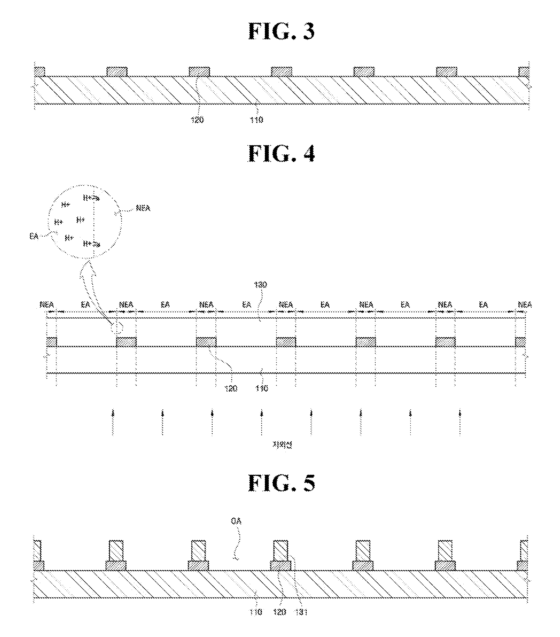
[0088]Resin BM (Cheil Industries Inc.) was coated on transparent glass substrates with dimensions of about 730 mm wide, about 920 mm long, and about 0.7 mm thick (1737 glass, Corning), followed by exposure and development, to form about 15.0″ XGA light-shielding patterns. The light-shielding patterns had a thickness of about 15 μm.
[0089]Next positive-type photoresist films (HKT601, Clariant) were formed to a thickness of about 3.0 μm on the glass substrates, and dried.
[0090]Next, UV light was illuminated on the rear surfaces of the glass substrates using a UV exposure machine (CT-2000PPM, Cleantech) including a low-pressure mercury lamp with an effective wavelength of about 254 nm. At this time, the amount of UV energy per unit area of the glass substrates was about 500 mJ.
[0091]Next, the photoresist films were developed using about 0.67% potassium hydroxide (KOH) aqueous solution to form dummy barrier ribs on the light-shielding patterns.
[0092]Next, RGB inks (Donjin Semichem Co., L...
PUM
 Abstract
Description
Claims
Application Information