Low friction chain

Active Publication Date: 2008-01-24
TSUBAKIMOTO CHAIN CO
View PDF11 Cites 25 Cited by
  • Summary
  • Abstract
  • Description
  • Claims
  • Application Information

AI Technical Summary

Benefits of technology

[0010]The convex shape of the edge surfaces reduces the contact area between the link plates and the guide on which the chain slides, thereby reducing wear and improving combustion efficiency when the chain is used in an automobile engine.
[0011]As the chain having convex edge surfaces travels over the shoe of a chain guide, lubricating oil enters a relatively wide gap between the guide and a front portion of a link plate, and proceeds toward a narrow gap between the guide and the highest part of the back of the link plate, i.e., the part that is farthest from a pitch line connecting the centers of the pin holes or bushing holes of the link plate. As a result, a wedge film effect is generated in which lubricating oil is drawn into a gap, which becomes progressively narrower in the direction of movement of the oil. As the oil is drawn into the gap, its velocity increases, producing a load-sustaining pressure. Further description of the wedge film effect can be obtained from “Lubrication Terms Collection”, Japanese Lubrication Institution, Jul. 20, 1981. Furthermore, Couette's flow is produced by movement of the chain over the surface of a guide. Couette's flow is a flow produced between two plates when a space between the plates is filled with fluid and one of the plates is moved in parallel with the other plate. Further description of Couette'

Problems solved by technology

The straight edges of the plates 400 come into sliding contact with the shoe surface Ga of a guide G over a relatively large area, with a resulting high friction loss, and increased fuel consumption when the chain is used as a timing chain.
Other roller chains have gourd-shaped link plates,

Method used


Image

  • Low friction chain
  • Low friction chain
  • Low friction chain

Examples


Example

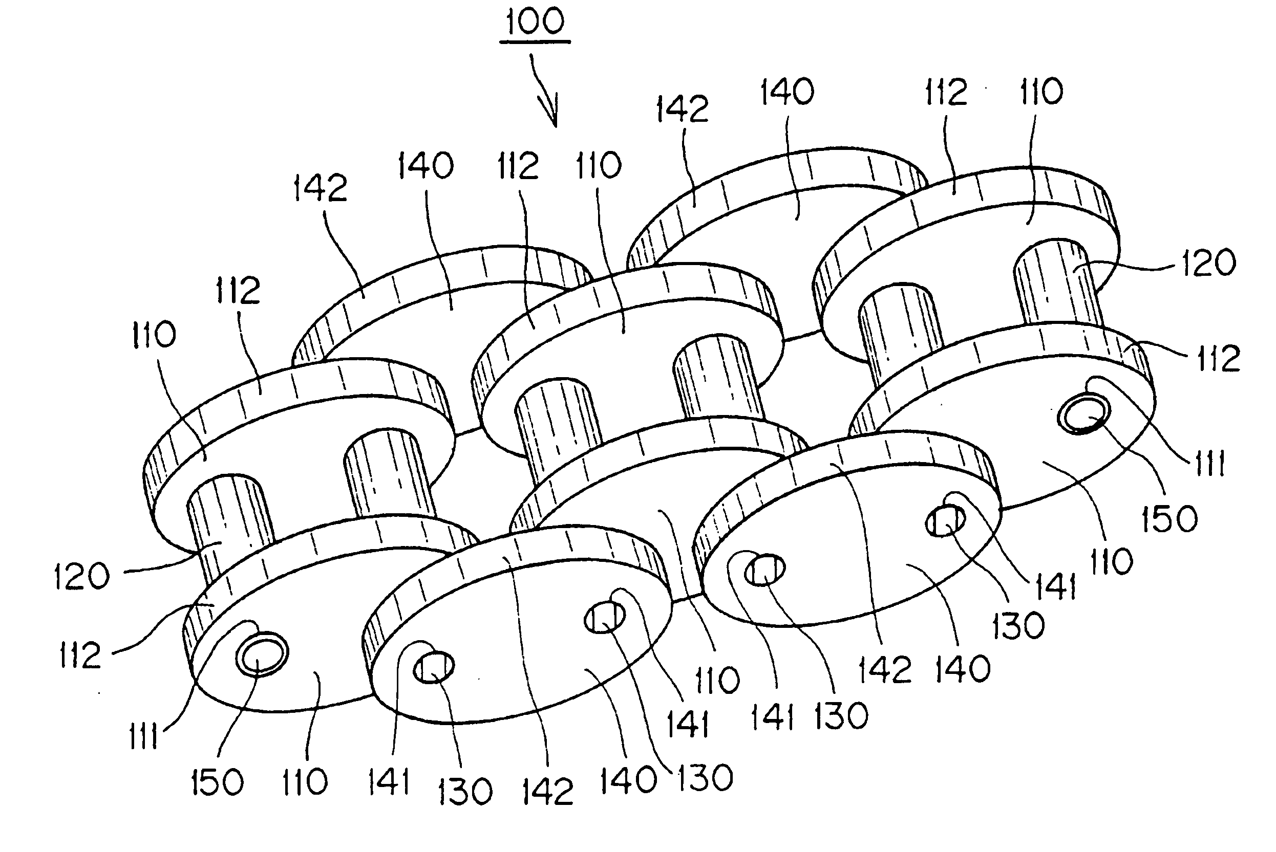
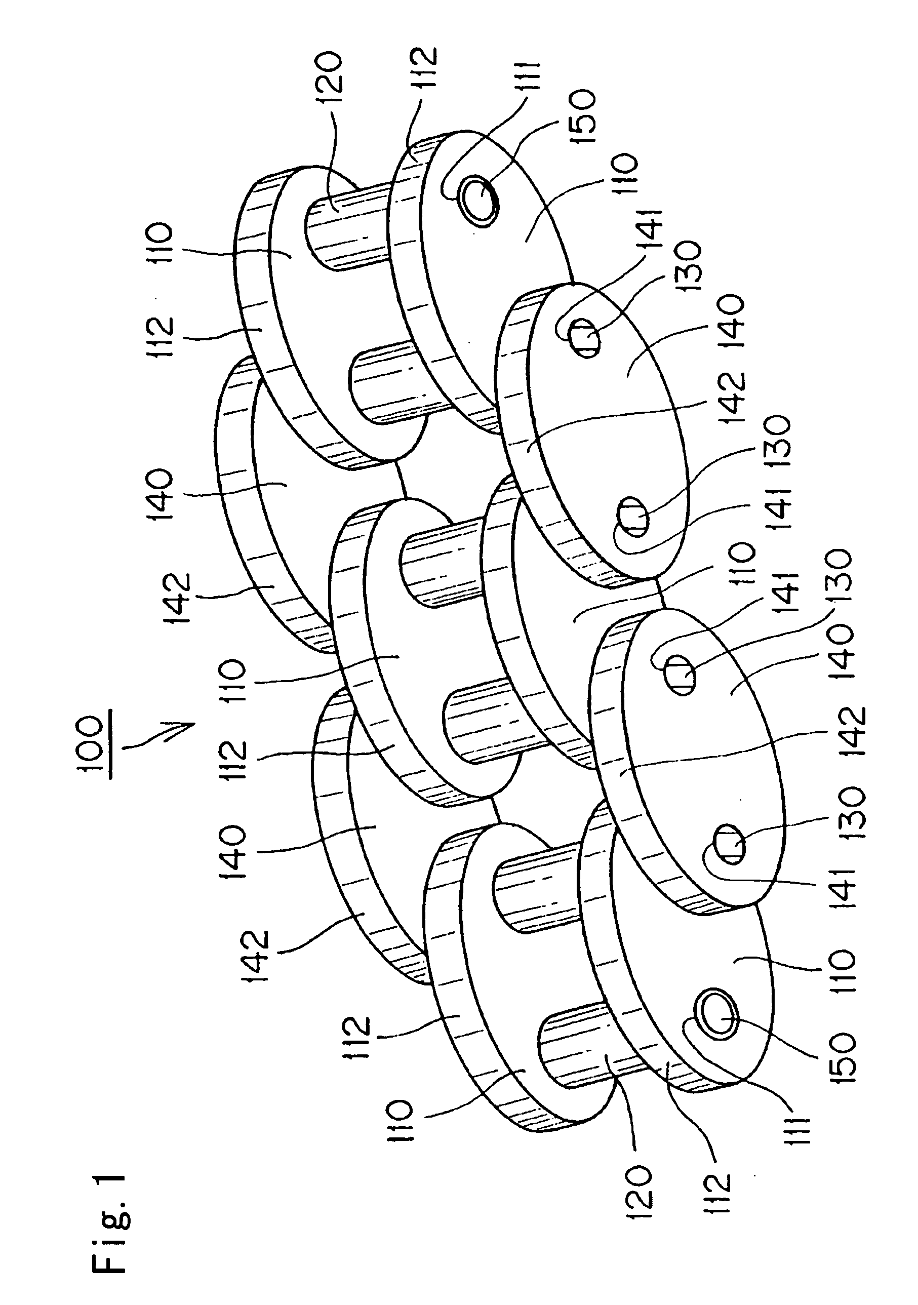
[0021]The low friction chain 100, shown in FIG. 1, comprises pairs of spaced, opposed, right and left inner plates 110, bushings 150 press-fit into bushing holes 111 in plates 110, rollers 120 rotatable on the bushings 150, connecting pins 130 extending through the bushings 150 and rotatable therein, and pairs of spaced, opposed, right and left outer plates 140, having pin holes 141 into which the ends of pins 140 are press-fit. The pins 140 thus flexibly interconnect alternating links of a first set and second set, the first set being composed of links having inner link plates connected by bushings 150, and the second being composed of links having outer link plates connected by connecting pins 130.

[0022]In the embodiment shown in FIG. 1, both the inner plates 110 and the outer plates 140 are formed with upper and lower edges that are convex when viewed along a direction parallel to the direction of elongation of the connecting pins.

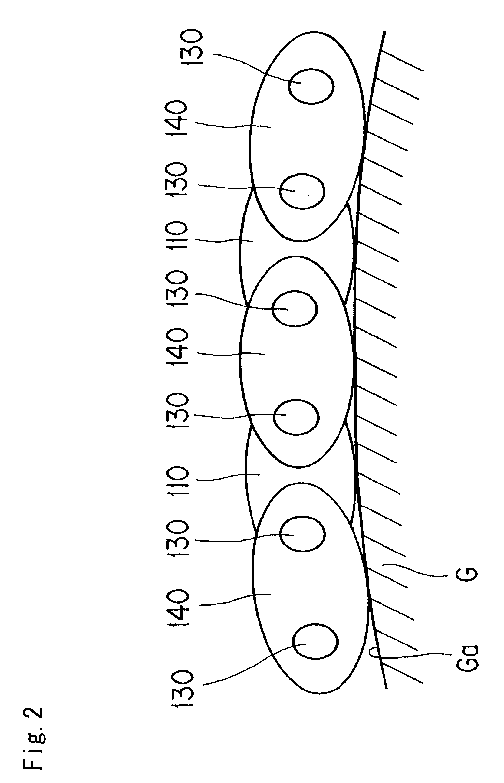
[0023]As shown in FIG. 2, the chain 100 travels i...


PUM


Abstract

A low friction roller chain, bushing chain or silent chain is composed of links in which at least some of the link plates have convex and/or grooved edge surfaces adapted to slide on the surface of a chain guide.

Description

CROSS-REFERENCE TO RELATED APPLICATION[0001]This application claims priority on the basis of Japanese patent application 2006-199968, filed Jul. 21, 2006. The disclosure of Japanese application 2006-199968 is hereby incorporated by reference.FIELD OF THE INVENTION[0002]This invention relates to chains used in power transmission mechanisms for use in industrial machines, vehicles, conveyors and the like, and more particularly to the reduction in friction in a chain transmission. The invention has particular utility as a low friction chain in the timing drive of an automobile engine.BACKGROUND OF THE INVENTION[0003]In a typical chain transmission, a chain is in mesh with the teeth of a driving sprocket and one or more driven sprockets. In an automobile engine, for example, the timing chain transmits poser from a sprocket on the engine crankshaft to one or more valve-operating camshafts. The chain is typically in sliding contact with several guides, one being a fixed guide in contact w...

Claims


Application Information

Patent Timeline
IPC IPC(8): F16G13/04
CPCF16G13/02F16G13/06F16G13/04
Inventor TOHARA, TAKASHIHASHIMOTO, HIROSHINAKAJIMA, TOSHIYUKI
Owner TSUBAKIMOTO CHAIN CO
Why Eureka
Try Eureka