Compressor

a compressor and reciprocating technology, applied in the field of compressors, can solve the problems of reducing the rotation speed of the rotor b>22/b>, affecting the suction efficiency of refrigerant, and the reciprocating type compressor of the related art cannot be used, so as to improve the suction efficiency, reduce the difficulty of drawing refrigerant, and slow compression

Inactive Publication Date: 2008-01-31
LG ELECTRONICS INC
View PDF5 Cites 12 Cited by
  • Summary
  • Abstract
  • Description
  • Claims
  • Application Information

AI Technical Summary

Benefits of technology

[0009]An object of the present invention designed to solve the foregoing related art problems lies on providing a compressor which enables relatively slow compression, and relatively fast suction of refrigerant for improving a suction efficiency, and reducing a torque of the electric driving part.
[0010]To achieve the object of the present invention, there is provided a compressor including a cylinder block for compressing, discharging, and drawing refrigerant, a piston for reciprocating inside of the cylinder block, a crank shaft for rotating as the crank shaft receives a torque from an electric driving part, and having an eccentric part at an end thereof, a connecting rod having one end coupled to the piston, and the other end coupled to the eccentric part at the crank shaft for converting rotating movement of the crank shaft into a linear movement to move the piston, and a supplementary torque providing part for reducing a speed of the piston in compression of the refrigerant, and accelerates a speed of the piston in drawing the refrigerant.

Problems solved by technology

However, the related art reciprocating type compressor can not, but be involved in over compression due to a generally fast compression rate in compressing the refrigerant.
Of course, the rotation speed of the rotor 22 may be reduced for solving the problem, however, when the suction rate of the refrigerant becomes slow, to cause difficulty in drawing the refrigerant.

Method used


Image

  • Compressor
  • Compressor
  • Compressor

Examples


first embodiment

[0029]Referring to FIGS. 3A˜3C, a first embodiment suggests positioning of the supplementary torque providing part such that compression and restoration of the supplementary torque providing part are made along a direction of movement of the piston 340.

[0030]For this, the supplementary torque providing part includes a first elastic member 410 having one end fixed to one stationary part inside of the compressor, and the other end in contact with the eccentric part 320 for extending or contracting along a moving direction of the piston 340 in compression of the refrigerant to increase a level of torque storage therein.

[0031]That is, the first elastic member 410 is a plate spring in contact with an outside circumferential surface of the eccentric part 340 so that the first elastic member 410 provides a restoration force to the eccentric part 320 in a direction opposite to the moving direction of the piston 340 in compression of the refrigerant, and, particularly, the first elastic memb...

second embodiment

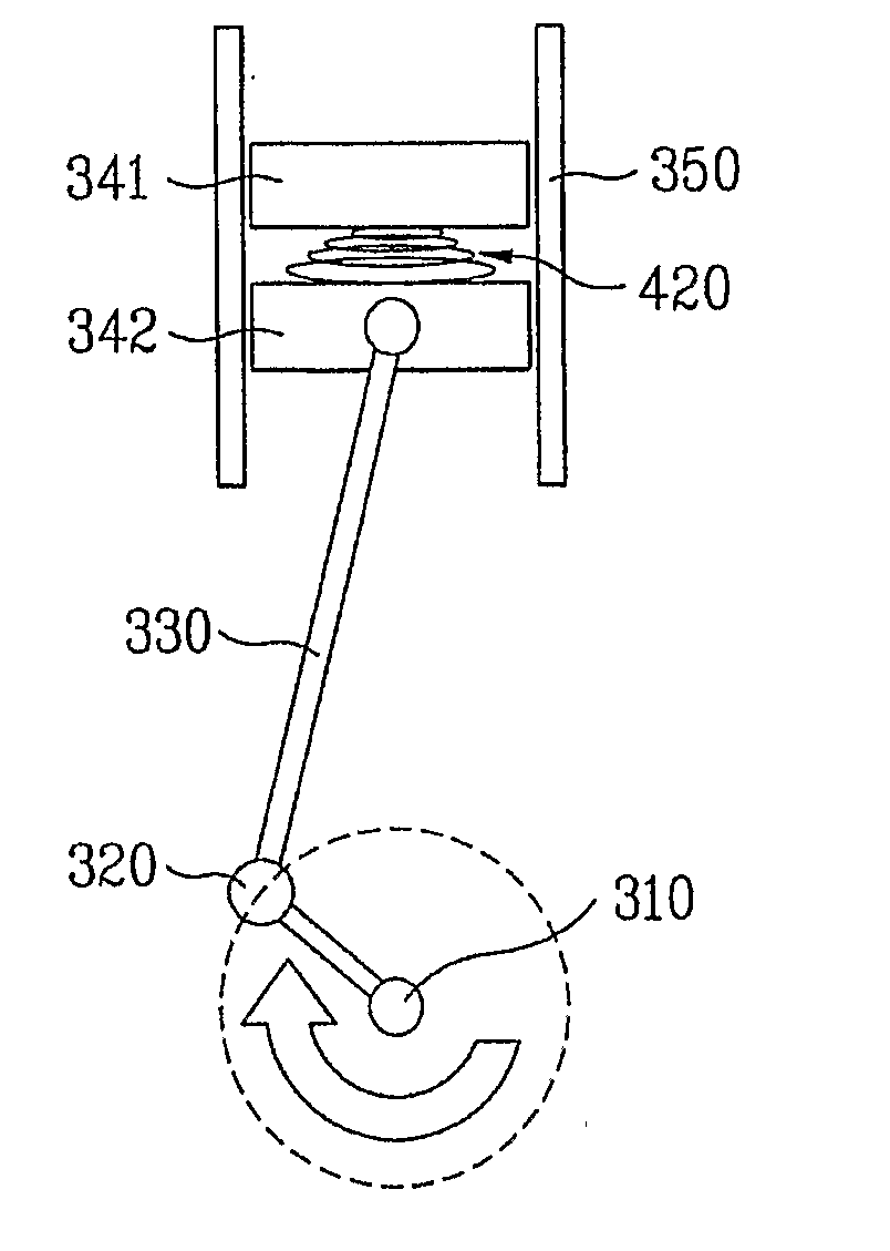
[0042]That is, the present invention suggests fitting a supplementary torque providing part in the piston 340. For this, the piston 340 includes a first piston 341, and a second piston 342, and the supplementary torque providing part is provided between the pistons 341 and 342, with both ends thereof connected to the pistons 341 and 342.

[0043]The supplementary toque providing part includes a second elastic member 420 which is compressed when the refrigerant is compressed, and restored when the refrigerant is drawn. The supplementary torque providing part 420 is either a coil spring, or a plate spring.

[0044]Particularly, as shown, the second embodiment suggests the second elastic member 420 to be a conical coil spring that has a diameter which becomes the greater as it goes toward a side connected to the connected rod 330 the more.

[0045]Of course, the piston 340 may include, not only two pieces of pistons 341, and 342, but also a plurality of pieces of pistons, more than three, when ...

third embodiment

[0057]Referring to FIGS. 6A˜6C, a third embodiment suggests providing the supplementary torque providing part to the connecting rod 330.

[0058]For this, the connecting rod 330 is divided into a first connecting part 331 and a second connecting part 332, and the supplementary torque providing part is provided between the first connecting part 331 and the second connecting part 332. The first connecting part 331 is connected to the piston part 340, and the second connecting part 332 is connected to the eccentric part 320.

[0059]Moreover, the supplementary torque providing part includes at least one third elastic member 430 having opposite ends connected to opposite surfaces of the first connecting part 331 and the second connecting part 332. The third elastic member 340 is a plate spring, and connected to the connecting parts 331 and 332 with at least one of joining type, selected from bolt, screw, rivet, and welding.

[0060]That is, referring to FIG. 6A, in the third embodiment of the pr...


PUM


Abstract

Compressor including a supplementary torque providing part for reducing a speed of a piston (340) in compression of refrigerant, and increasing the speed of the piston (340) in drawing of the refrigerant, thereby reducing a compression rate of the refrigerant in compression relatively, and increasing a re-expansion rate, to maximize a suction efficiency.

Description

TECHNICAL FIELD[0001]The present invention relates to compressors, and more particularly, to a reciprocating type compressor, in which a compression rate of refrigerant is reduced relatively, a re-expansion rate is increased, for maximizing a suction efficiency.BACKGROUND ART[0002]In general, the compressor receives a working fluid from an evaporative heat exchanger, compresses, and supplies the working fluid to a condensing heat exchanger. FIG. 1 illustrates a related art reciprocating type compressor that compresses a gas inside of a cylinder by means of reciprocating motion of a piston connected to a connecting rod, which will be described.[0003]The reciprocating type compressor is provided with a case 10, an electric driving part 20, and a compression part 30. The case 10 has an upper shell 11 and a lower shell 12, joined together to enclose an inside space of the case 10. There is a refrigerating machine oil held in a lower part of an inside of the lower shell 11 to an appropri...

Claims


Application Information

Patent Timeline
Patent Type & Authority Applications(United States)
IPC IPC(8): F25B1/02F02B75/04F04B39/00F16C3/26F16C7/04
CPCF02B75/04F02B75/044F02B75/045F16C7/04F04B39/0022F16C3/26F04B39/0005
Inventor KIM, HYUNBAE, JI YOUNGROH, CHUL GIJANG, CHANG YONGSIN, JONG MIN
Owner LG ELECTRONICS INC
Why Eureka
Try Eureka